Cisco APIC 5.2(1g) released

New software features
Alias, Annotations, and Tags
Several methods are provided for adding label metadata to objects.
To simplify the identifying, addressing, and grouping of objects, ACI provides several methods for the user to add label metadata to objects. These methods are summarized in the list below:
- Name Alias: A cosmetic substitute for a GUI entity.
- Global Alias: A label, unique within the fabric, that can serve as a substitute for an object's Distinguished Name (DN).
- Tag Instance / Annotation: A simple note or description.
- Policy Tag: A label for grouping of objects, which need not be of the same class.
Automatic FPGA/EPLD/BIOS upgrade
Switches will automatically upgrade the FPGA/EPLD/BIOS based on the booting Cisco ACI switch image during a normal boot-up sequence for certain components, even if it’s not an upgrade operation performed through the APICs.
Starting from Cisco APIC release 5.2(1) and ACI switch release 15.2(1), ACI switches will automatically upgrade the FPGA/EPLD/BIOS based on the booting ACI switch image during a normal boot up sequence for the following components, even if it’s not an upgrade operation performed through the APICs:
- Leaf switches and box-type spine switches: EPLD/FPGA/BIOS is automatically upgraded on the switch itself
- Modular-type spine switches: EPLD/FPGA/BIOS is automatically upgraded on these components:
- Supervisor module
- Linecard module
- Fabric module
When one of the supported components listed above boots up, the system automatically performs the following actions to determine if the EPLD/FPGA/BIOS image is in sync with the Cisco ACI or NX-OS image:
- The system compares the BIOS versions and performs an upgrade at the BIOS level if it finds that the images are out of sync.
- The system compares the EPLD/FPGA versions and performs an upgrade at the EPLD/FPGA level if it finds that the images are out of sync.
- If the system has to perform an upgrade at any of the levels (at the BIOS level or at the EPLD/FPGA level), the system then performs a power cycle on that component (the switch, supervisor module, linecard module, or fabric module).
These automatic FPGA/EPLD/BIOS upgrades during a normal boot up sequence is performed per component. For instance, when a new linecard module is inserted and boots up with the base ACI switch image downloaded from the supervisor module, only the new linecard module is power-cycled to apply the FPGA/EPLD/BIOS from the base ACI switch image. Other modules will not be impacted.

Disabling dataplane IP address learning per endpoint or subnet
You can disable dataplane IP address learning per endpoint or subnet. Previously, you could only disable dataplane IP address learning per VRF instance or bridge domain.
Dynamic MAC address detection for a Layer 3 policy-based redirect destination
You can configure any of the Layer 3 policy-based redirect (PBR) destinations without specifying a MAC address, which causes the leaf switches to use the Address Resolution Protocol (ARP) to determine the MAC address of the PBR next-hop. The benefit is that you do not need to check the MAC address of each PBR destination and an active-standby HA pair does not need to use a floating MAC address.
End of support for device packages
Device packages are no longer supported. There is no longer a managed mode for devices; all devices are effectively unmanaged.
All device package-related information was removed from the Cisco APIC Layer 4 to Layer 7 Services Deployment Guide, Release 5.2(x).
EPG and tag selectors for ESGs
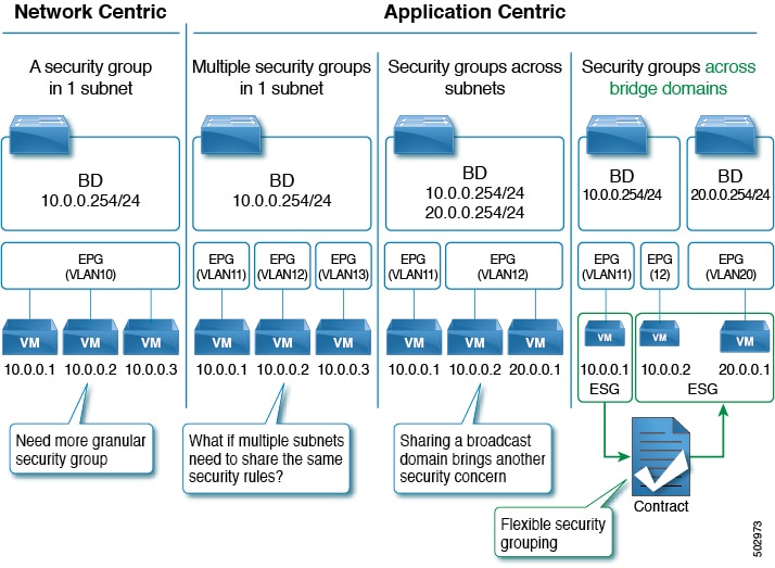
Endpoint group (EPG) selectors can add specific EPGs to an endpoint security group (ESG). Tag selectors can add objects to an ESG based on policy tags.
Selectors are configured under each ESG with a variety of matching criteria to classify endpoints to the ESG. Unlike EPGs, which use VLANs to classify endpoints, ESGs can classify endpoints using much more flexible criteria. This concept is similar to micro segmentation EPG (or useg EPG); however, useg EPGs are still tied to one bridge domain while ESGs can contain endpoints across bridge domains.
The supported ESG selectors are:
- Tag Selector: Matches endpoints based on policy tags that are assigned to a variety of attributes such as MAC and IP addresses, virtual machine (VM) tags, virtual machine names [vm name], subnet tags, and static endpoint tags. ESG tag selectors can match only policy tags in the same tenant as the ESG. The tag selector is introduced in Cisco APIC Release 5.2(1).
- EPG Selector: Matches all endpoints in a specific EPG, and the ESG will inherit all contracts configured under the EPG. This selector allows users to migrate security configurations from EPG to ESG seamlessly. ESGs can use EPG selectors only for EPGs in the same VRF as the ESG. The EPG selector is introduced in Cisco APIC Release 5.2(1).
- IP Subnet Selector: Matches endpoints based on the host IP address or IP subnet. Tag selectors provide the same capability via policy tags. The IP subnet selector is introduced in Cisco APIC Release 5.0(1).
HTTP URI tracking
You can track service nodes using the HTTP URI.
Guides and limitations on HTTP URI tracking:
- Tracking supports both IPv4 and IPv6.
- Tracking supports only HTTP, not HTTPS.
- Tracking supports only HTTP version 1.0 and 1.1.
- The destination port must be 80.
- You must configure the URI (not the URL). Domain resolution is not supported.
- The URI must not be empty and must start with "/".
- Tracking supports 100 probes per leaf switch and 1500 per fabric. The values are the total of ICMP, L2ping, TCP, and HTTP probes.
- The minimum frequency should be 5 seconds. In standalone NX-OS, the minimum frequency is 60 seconds.
MACsec support on N9K-X9716D-GX
MACsec is now supported on the Cisco N9K-X9716D-GX line card.
Next-hop propagation supported with OSPF and static routes redistributed in BGP for floating L3Outs
Beginning with release 5.2(1), next-hop propagation is supported with OSPF and static routes redistributed in BGP for floating L3Outs. Prior to release 5.2(1), next-hop propagation was supported with BGP only for floating L3Outs.
Policy-based redirect destination in an L3Out
A policy-based redirect destination can now be in an L3Out.
Beginning with Cisco Application Policy Infrastructure Controller (APIC) release 4.1(2), you can use an L3Out to connect a Layer 4 to Layer 7 services device that is part of a service graph. There are multiple ways to use an L3Out as part of a policy-based redirect (PBR) service graph:
- Using PBR to redirect only to the consumer interface of the Layer 4 to Layer 7 services device, while the provider interface of the Layer 4 to Layer 7 services device is connected to an L3Out. This is referred to as "uni-directional" PBR, because PBR is done only for one direction of the traffic. This option was introduced in Cisco APIC release 4.1(2).
- Using PBR to redirect only to the provider interface of the Layer 4 to Layer 7 services device, while the consumer interface of the Layer 4 to Layer 7 services device is connected to an L3Out. This option was introduced in Cisco APIC release 5.0(1), which is also a uni-directional PBR design, and it is the symmetric design of the one described in the previous bullet.
- Using PBR to redirect a Layer 4 to Layer 7 services device interface that is connected to an L3Out. This option was introduced in Cisco APIC release 5.2(1).
These use cases are described in greater detail in the text that follows.
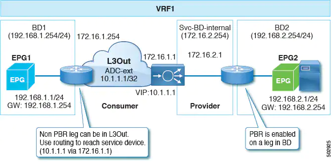
As mentioned in the first bullet, beginning with Cisco APIC release 4.1(2), you can configure unidirectional PBR to a consumer interface, and can connect the provider interface to an L3Out as shown in the following illustration:
In the example, PBR is enabled in the consumer connector in the bridge domain, but PBR is not enabled on the provider connector in the L3Out. This design is supported only when L3Out is the provider connector of the last service node. Prior to the Cisco APIC 4.1(2) release, if PBR was configured to redirect traffic to a node of a service graph, both the consumer and provider connectors of the Layer 4 to Layer 7 services device had to be in a bridge domain, even in the case of uni-directional PBR.
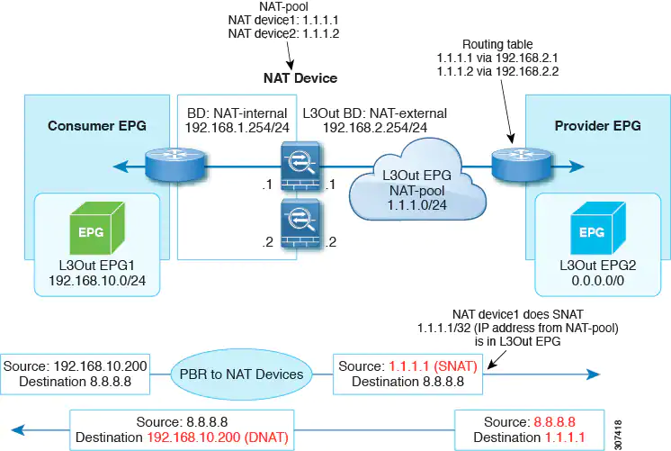
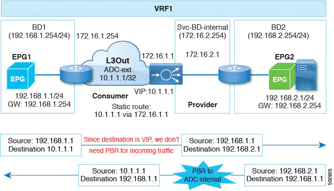
Beginning with Cisco APIC release 5.0(1), uni-directional PBR is supported with the other connector in an L3Out, regardless if the L3Out is the provider or consumer connector and regardless if the L3Out is the last node or not. This includes the case where the load balancer has a VIP address outside of the local subnet on the consumer side of the service node, as shown in the following illustration.
In the following illustration example, the incoming traffic from the consumer endpoint to the VIP address is forwarded to the load balancer that is connected to the L3Out, based on the routing table. Then, the traffic is forwarded to the provider endpoint. The return traffic from the provider endpoint to the consumer endpoint is redirected to the provider side of the service node because of PBR.
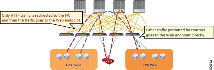
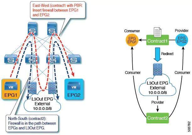
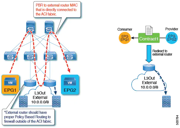
Beginning with Cisco APIC release 5.2(1), the Layer 4 to Layer 7 services device that is used as a destination of the PBR policy can have the interfaces in an L3Out. Prior to this release, a PBR policy's destination interface could only be in a bridge domain. Some common use cases include:
- You can use the same firewall for both East-West and North-South traffic. In this case, the firewall internal leg is connected to the Cisco Application Centric Infrastructure (ACI) fabric, while the firewall external leg is outside of the Cisco ACI fabric.
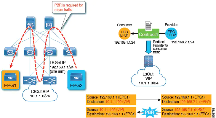
- You can have a one-arm load balancer with a VIP address that is outside of the local subnet. In this case, the VIP address is outside of the load balancer's self IP address subnet. The load balancer does not perform Source Network Address Translation (SNAT), and thus PBR is required for the return traffic.
- You can redirct traffic to a device, such as an external firewall, that is not directly connected to Cisco ACI.
When using a service graph with PBR with a bridge domain, Cisco ACI automatically creates a hidden EPG called a service EPG. Cisco ACI configures contracts between the service EPG and user-created EPGs to allow the traffic path as defined by the service graph. When connecting a Layer 4 to Layer 7 services device interface to an L3Out and using this interface as a PBR destination for a service graph, the L3Out EPG that the administrator must create also performs the same function as the dynamically created service EPG for a regular service graph PBR configuration. With the L3Out EPG used for a PBR destination interface, some of the traffic is forwarded to the Layer 4 to Layer 7 interface using PBR, while other traffic must be sent using regular traffic forwarding (routing). To enable the communication from an EPG to a L3Out EPG used by the Layer 4 to Layer 7 appliance you must configure a contract. The following table illustrates in which cases you can configure a contract between an L3Out EPG used by a PBR destination interface and another L3Out EPG or a regular EPG:
EPG1 | EPG2 | Notes |
|---|---|---|
L3Out EPG (PBR destination in an L3Out) | EPG or L3Out EPG | Supported. You can create a contract between the L3Out EPG used for the PBR destination in the L3Out and the existing EPG/L3Out EPG. |
L3Out EPG (PBR destination in an L3Out) | Service EPG in a bridge domain | Not supported. |
Service EPG in a bridge domain (PBR destination in a bridge domain) | Service EPG in a bridge domain, consumer/provider EPG, or consumer/provider L3Out EPG | Supported. You must enable Direct Connect. |
Remote leaf peer-link support
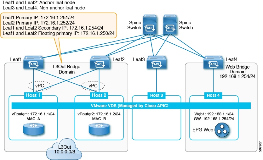
Beginning with Cisco APIC Release 5.2(1), you can connect remote leaf switch pairs directly to each other ("back-to-back") by fabric links to carry local east-west traffic. An example of a scenario with significant east-west data traffic is unicast traffic from an EPG to an L3Out in a vPC pair, as shown in the figure below.
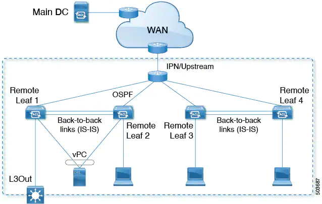
Only traffic between non-vPC connected hosts traverses the back-to-back links. A vPC connected host can send traffic locally from the remote leaf switch nearest the destination, so such traffic will not use the back-to-back links.
When uplinks and a back-to-back connection are active between a pair of remote leaf switches, the back-to-back links are preferred for east-west traffic, while the uplinks carry traffic to and from any other remote leaf switches and switches in the main datacenter.
Although the remote leaf architecture normally calls for a spine switch or the IPN router to route traffic between proximately located remote leaf switches, a direct back-to-back leaf connection can save bandwidth on the upstream device.
Simplified ESG migration
Beginning with Cisco APIC Release 5.2(1), EPG selectors allow ESGs to inherit contracts from EPG, simplifying EPG-to-ESG migration. The contract inheritance with EPG selectors enables a seamless and flexible migration by allowing endpoints to keep communicating with other endpoints via inherited contracts even though the other endpoints are not yet migrated to ESGs.
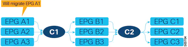
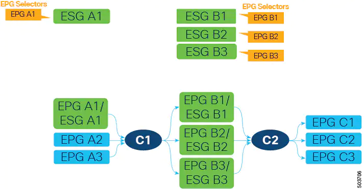
In the following example, we will focus on the EPG to ESG migration of EPG A1 in the following figure. The current communication from EPG A1 is done through contract C1 with EPGs B1, B2, and B3.
The first step is to create an ESG (ESG A1 in the following figure) and match EPG A1 to it using the EPG selector.
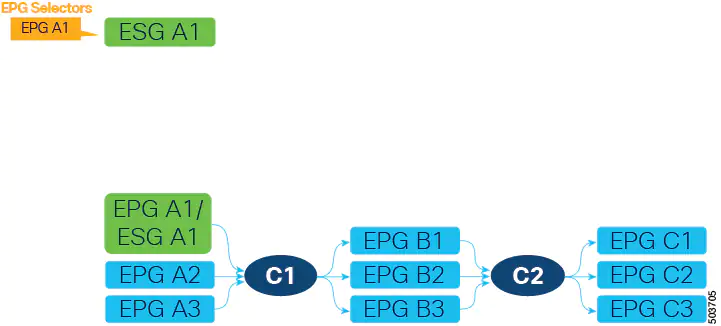
After EPG A1 has been matched to ESG A1, endpoints that belonged to EPG A1 now belong to ESG A1 and contract C1 provided by EPG A1 is inherited by ESG A1. All of the migrated endpoints can still communicate with EPGs B1, B2, and B3 even though these EPGs are not migrated to ESG yet. Remember that without the contract inheritance with EPG selectors, ACI does not allow contracts between ESG and EPG. Note that when an ESG inherits contracts via EPG selectors, the original pcTags of the EPGs are replaced by the pcTag of the ESG. This operation may result in a small transient disruption of traffic for endpoints in the EPGs.
At this point, depending on your project schedule, instead of completing the migration of EPG A1, you could configure new contracts between ESG A1 and other ESGs or L3Out external EPGs. However, no more new contracts can be added to EPG A1 because all security configurations should be managed by the ESG. To keep the configuration simple and maintainable, we recommend that you complete the EPG to ESG migration at your earliest convenience. Until EPG A1 stops providing (or consuming) contracts, a fault F3602 is raised as a warning to make you aware of an incomplete migration.
To continue the migration, create ESGs for the EPGs on the other side of contract C1. In this example, EPG A1 is providing contract C1, so those EPGs (EPGs B1, B2, and B3) are consuming contract C1. Migrate these EPGs to new ESGs (ESGs B1, B2, and B3) using EPG selectors. In this example in the following figure, each EPG is mapped to an ESG.
Alternatively, you could combine multiple EPGs into one ESG. For example, you could create one ESG and then configure an EPG selector for both EPG B1 and B2 on the same ESG.
Next, create a new contract (C1’ in the following figure) with the same filters as contract C1. Configure the new ESGs as provider and consumer. This is in preparation to stop providing contract C1 from EPG A1, which is the last step of EPG to ESG migration for EPG A1.
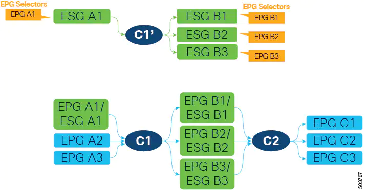
Because contract C1 with the same filters was already inherited by all four ESGs (A1, B1, B2, and B3), the new contract configuration does not deploy any new rules in hardware, so no additional policy TCAM is consumed by creating the new contract.
ESG A1 now has contract C1’ that allows the same communication as C1 with ESG B1, B2, and B3. At this point, we can stop providing contract C1 on EPG A1, allowing the ESG A1 to handle all security, as shown in the following figure.
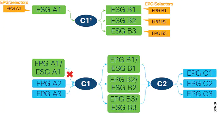
Keep in mind that EPGs B1, B2, and B3 cannot stop consuming contract C1 yet because contract C1 is also provided by EPGs A2 and A3, which are not yet migrated to ESGs. After EPGs A2 and A3 are migrated to ESGs and are providing contract C1’, all EPGs (A2, A3, B1, B2, and B3) can stop using contract C1 without traffic disruption.
To complete the migration of EPG to ESG, follow the same procedure for contract C2 and any other contracts on an EPG level.
Site-of-Origin (SoO)
The site-of-origin (SoO) extended community is a BGP extended community attribute that is used to identify routes that have originated from a site so that the readvertisement of that prefix back to the source site can be prevented. The SoO extended community uniquely identifies the site from which a router has learned a route. BGP can use the SoO value associated with a route to prevent routing loops.
Valid formats are:
- extended:as2-nn2:<2-byte number>:<2-byte number>
For example:extended:as2-nn2:1000:65534 - extended:as2-nn4:<2-byte number>:<4-byte number>
For example:extended:as2-nn4:1000:6554387 - extended:as4-nn2:<4-byte number>:<2-byte number>
For example:extended:as4-nn2:1000:65504 - extended:ipv4-nn2:<IPv4 address>:<2-byte number>
For example:extended:ipv4-nn2:1.2.3.4:65515
When configuring the SoO for the User Tenant L3Outs, make sure not to configure the same SoO value as that of the global Fabric, Pod, or Multi-Site SoO configured within the ACI fabric. You can view the Fabric, Pod, and Multi-Site SoO values configured within the fabric by executing the following command on the switch:
show bgp process vrf overlay-1 | grep SOO
Software maintenance upgrade patches
You can install software maintenance upgrade (SMU) patches that contain fixes for specific defects. Because SMU patches can be released much more quickly than a more traditional patch release, you can resolve specific issues in a more timely manner.
Cisco APIC cluster connectivity to the fabric over a Layer 3 network
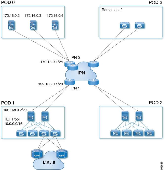
Beginning with Cisco APIC Release 5.2(1), Cisco ACI supports a topology in which the APIC cluster is separated from the ACI fabric by a layer 3 inter-pod network (IPN). This topology allows the APIC cluster to be in a separate security zone from the fabric. APIC cluster connectivity to the fabric over a layer 3 network is similar to Cisco ACI Multi-Pod with the exception that the pod containing the APIC cluster contains no fabric nodes and the fabric pod contains no APICs.
The following figure shows an example of a layer 3 connected APIC cluster topology.
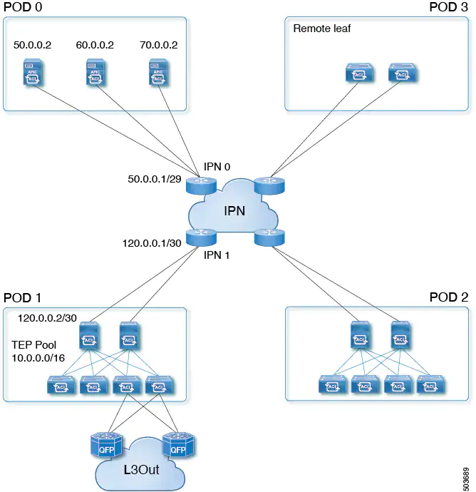
The layer 3 connected APIC cluster is able to discover the fabric nodes across the IPN using the following protocols:
- The IPN performs DHCP relay from the fabric pods (such as Pod 1) to the layer 3 connected APIC cluster (Pod 0).
- A fabric pod advertises its TEP pool to the IPN by OSPF.
- The IPN advertises the APIC subnets to the spines by OSPF.
Guidelines and Restrictions for Deploying APIC Cluster Connectivity to the Fabric Over a Layer 3 Network
- APIC Cluster Connectivity to the Fabric Over a Layer 3 Network can be configured only for a new APIC cluster. An existing APIC cluster can be converted to a layer 3 connected APIC cluster only after erasing its setup.
- APICs in a layer 3 connected APIC pod cannot form a cluster with APICs in the fabric pod.
- APIC Cluster Connectivity to the Fabric Over a Layer 3 Network does not support vAPIC or vPOD.
- APIC Cluster Connectivity to the Fabric Over a Layer 3 Network supports standby APIC.
- APIC Cluster Connectivity to the Fabric Over a Layer 3 Network supports strict mode. In strict mode, you must approve the controller explicitly.
- You can use the infra VLAN to connect to the IPN router or you can use a different VLAN.
- We recommend that you retain an end-to-end DSCP value of 46 between the layer 3 connected APIC cluster and the fabric. This ensures the prioritizing of control traffic between the cluster and fabric. These configurations should be implemented on the cluster-facing IPN and on the fabric-facing IPN.
We further recommend that you deploy a policer on the cluster-facing IPN to prevent drops on traffic with a DSCP value of 46. For traffic with a DSCP value other than 46, the policer should be configured for 4 Gbps with pol_burst of 60 Mbps.
Support for intra-EPG contracts on L3Out EPGs
Beginning in Cisco APIC release 5.2(1), intra-EPG contracts are supported on L3Out EPGs.
- The action can be permit, deny, or redirect. The redirect action requires a service graph with policy-based redirect (PBR).
- An L3Out EPG with an IP address and subnet of 0.0.0.0/0 or 0::0 cannot use an intra-EPG contract nor intra-EPG isolation. The Cisco APIC raises a fault in these cases. However, you can instead use an IP address and subnet of 0.0.0.0/1 and 128.0.0.0/1 for the L3Out EPG to catch all traffic.
- Unlike an intra-EPG contract on an EPG, the implicit deny rule is not automatically added for an intra-EPG contract on an L3Out EPG. You must enable intra-EPG isolation to deny other traffic. Intra-EPG isolation on an L3Out EPG works only when the VRF instance is in the enforced mode.
- Cisco ACI cannot control how traffic reaches the Cisco ACI border leaf switch for intra L3Out enforcement.
Support for multiple next-hops to be propagated in the Cisco ACI fabric for redistributed routes in BGP for floating L3Outs
Support is available for multiple next-hops to be propagated in the Cisco ACI fabric for redistributed routes in BGP for floating L3Outs.
Support for the Telecom PTP profile (G.8275.1)
The precision time protocol (PTP) has a concept called the PTP profile. A PTP profile is used to define various parameters that are optimized for different use cases of PTP. Some of those parameters include, but not limited to, the appropriate range of PTP message intervals and the PTP transport protocols. A PTP profile is defined by many organizations/standards in different industries.
Synchronous Ethernet (SyncE)
Distributes high-quality clock frequency synchronization over Ethernet ports.
VMware enhanced LACP support for virtual Layer 4 to Layer 7 services devices
Enhanced LACP on interfaces of Layer 4 to Layer 7 virtual service devices used in service graphs is now supported.
Resolved issues
CSCvs47602
A bridge domain route is not leaked on the service ToR switch after re-triggering the service graph.
CSCvw12766
In a setup where there is already existing MDP confguration (spine and leaf nodes), after having deleted an MDP spine node, MDP tunnels and traffic might still be directed to that spine node. In the case of a new MDP spine node, the traffic might not get directed to the new spine node.
CSCvw84947
The BGP loop prevention feature for the inter-VRF shared service case does function as expected upon upgradeing to the 5.2(1) release with existing contracts for a brownfield environment. There is no impact if new contracts are used.
Compatibility information
Cisco NX-OS
15.2(1)
Cisco AVS
5.2(1)SV3(4.10)
For more information about the supported AVS releases, see the AVS software compatibility information in the Cisco Application Virtual Switch Release Notes, Release 5.2(1)SV3(4.11).
Cisco UCS Manager
2.2(1c) or later is required for the Cisco UCS Fabric Interconnect and other components, including the BIOS, CIMC, and the adapter.
CIMC HUU ISO
- 4.1(3b) CIMC HUU ISO (recommended) for UCS C220/C240 M5 (APIC-L3/M3)
- 4.1(2b) CIMC HUU ISO (recommended) for UCS C220/C240 M4 (APIC-L2/M2)
- 4.1(1g) CIMC HUU ISO for UCS C220/C240 M4 (APIC-L2/M2) and M5 (APIC-L3/M3)
- 4.1(1f) CIMC HUU ISO for UCS C220 M4 (APIC-L2/M2) (deferred release)
- 4.1(1d) CIMC HUU ISO for UCS C220 M5 (APIC-L3/M3)
- 4.1(1c) CIMC HUU ISO for UCS C220 M4 (APIC-L2/M2)
- 4.0(4e) CIMC HUU ISO for UCS C220 M5 (APIC-L3/M3)
- 4.0(2g) CIMC HUU ISO for UCS C240 M4 and M5 (APIC-L2/M2 and APIC-L3/M3)
- 4.0(2g) CIMC HUU ISO for UCS C220 M4 and M5 (APIC-L2/M2 and APIC-L3/M3)
- 4.0(1a) CIMC HUU ISO for UCS C220 M5 (APIC-L3/M3)
- 3.0(4l) CIMC HUU ISO (recommended) for UCS C220/C240 M3 (APIC-L1/M1)
- 3.0(4d) CIMC HUU ISO for UCS C220/C240 M3 and M4 (APIC-L1/M1 and APIC-L2/M2)
- 3.0(3f) CIMC HUU ISO for UCS C220/C240 M4 (APIC-L2/M2)
- 3.0(3e) CIMC HUU ISO for UCS C220/C240 M3 (APIC-L1/M1)
- 2.0(13i) CIMC HUU ISO
- 2.0(9c) CIMC HUU ISO
- 2.0(3i) CIMC HUU ISO
Network Insights Base, Network Insights Advisor, and Network Insights for Resources
For the release information, documentation, and download links, see the Cisco Network Insights for Data Center page.
For the supported releases, see the Cisco Data Center Networking Applications Compatibility Matrix.


Member discussion