Cisco APIC 5.2(3e) released

New software features
BGP underlay for Cisco ACI Multi-Pod and remote leaf switches
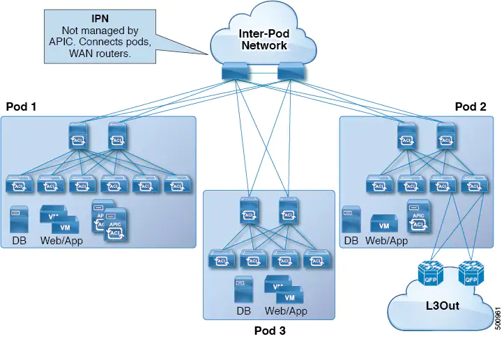
The border gateway protocol (BGP) is now available as an alternative to the Open Shortest Path First (OSPF) protocol for the Inter-Pod Network (IPN) underlay.
Multi-Pod enables provisioning a more fault-tolerant fabric comprised of multiple pods with isolated control plane protocols. Also, Multi-Pod provides more flexibility with regard to the full mesh cabling between leaf and spine switches. For example, if leaf switches are spread across different floors or different buildings, Multi-Pod enables provisioning multiple pods per floor or building and providing connectivity between pods through spine switches.
Multi-Pod uses MP-BGP EVPN as the control-plane communication protocol between the ACI spines in different pods.
In releases before Cisco APIC Release 5.2(3), OSPF is used in the underlay to peer between the physical spines and the IPN. Beginning with Cisco APIC Release 5.2(3), the underlay protocol can be OSPF or BGP (eBGP only) or a mixture, with some pods using OSPF and some using BGP.
Beginning with Cisco APIC Release 5.2(3), a fabric consisting of only two pods can be connected directly, without an IPN. For information about this Multi-Pod Spines Back-to-Back topology, see About Multi-Pod Spines Back-to-Back.
The remote leaf switches are added to an existing pod in the fabric. All policies deployed in the main data center are deployed in the remote switches, which behave like local leaf switches belonging to the pod. In this topology, all unicast traffic is through VXLAN over Layer 3. Layer 2 broadcast, unknown unicast, and multicast (BUM) messages are sent using Head End Replication (HER) tunnels without the use of Layer 3 multicast (bidirectional PIM) over the WAN. Any traffic that requires use of the spine switch proxy is forwarded to the main data center.
The IPN underlay protocol to peer between the remote leaf switches and the upstream router can be either OSPF or BGP. In previous releases, only an OSPF underlay is supported.
Cisco ACI Multi-Pod spine switches back-to-back
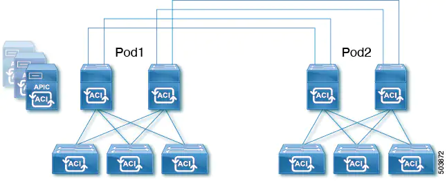
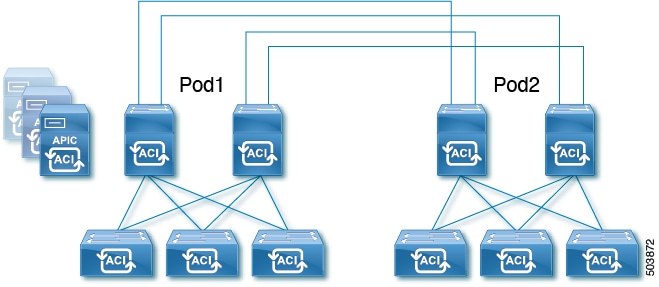
Beginning with Cisco APIC Release 5.2(3), the ACI Multi-Pod architecture is enhanced to support connecting the spines of two Pods directly with back-to-back ("B2B") links. With this solution, called Multi-Pod Spines Back-to-Back, the IPN requirement can be removed for small ACI Multi-Pod deployments. Multi-Pod Spines Back-to-Back also brings operational simplification and end-to-end fabric visibility, as there are no external devices to configure.
In the Multi-Pod Spines Back-to-Back topology, the back-to-back spine link interfaces are implemented as L3Outs in the infra tenant. These links are typically carried on direct cable or dark fiber connections between the Pods. Multi-Pod Spines Back-to-Back supports only Open Shortest Path First (OSPF) connectivity between the spine switches belonging to different Pods.
The following figure shows a Multi-Pod Spines Back-to-Back topology with back-to-back spines connected between Pod1 and Pod2:
Cisco NX-OS to Cisco ACI POAP auto-conversion
Cisco NX-OS to Cisco Application Centric Infrastructure (ACI) power-on auto-provisioning (POAP) auto-conversion automates the process of upgrading software images and installing configuration files on nodes that are being deployed in the network for the first time. When a Cisco NX-OS node with the POAP auto-conversion feature boots and does not find the startup configuration, the node enters the POAP mode and starts DHCP discovery on all ports. The node locates a DHCP server and bootstraps itself with its interface IP address, gateway, and DNS server IP addresses. The device also obtains the IP address of a TFTP server and downloads a configuration script that enables the node to download and install the appropriate software image and configuration file. This process converts the Cisco NX-OS node from the standalone mode to the Cisco ACI-mode.
To auto-convert a Cisco NX-OS node to a Cisco ACI node using POAP, you need to specify an interface on a Cisco ACI switch node that is connected to the Cisco NX-OS node that needs to be auto-converted. The interface specified on the Cisco ACI switch enables the handling of POAP and allows the Cisco NX-OS node to use the Cisco Application Policy Infrastructure Controller (APIC) as its DHCP server for auto-conversion. The Cisco ACI switch node must be already registered to the Cisco ACI fabric and be active, meaning that the node is reachable from the Cisco APIC cluster. This auto-conversion can be used both when adding a new switch to the fabric or when replacing an existing Cisco ACI switch.

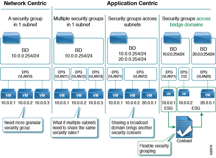
Endpoint security group enhancements
Endpoint security groups (ESGs) now support more features and configurations, such as:
- Inter-VRF service graphs between ESGs
- ESG shutdown
- Host-based routing/host route advertisement
- ESGs can be specified as a source or destination of the following features:
- On Demand Atomic Counter
- On Demand Latency Measurement
ERSPAN supports IPv6 destinations
No details are specified for this feature.
Integrity check for exported configuration files
Beginning with the 5.2(3) release, when you export a configuration file to an external server, the Cisco APIC calculates the MD5 checksum for the file contents and stores it in a MD5 file. This MD5 file gets exported along with the configuration file. When importing the configuration file, the Cisco APIC validates the file's integrity by comparing its current MD5 checksum with the value stored on the MD5 file, and the Cisco APIC informs you whether the integrity validation succeeds or fails. By default, this feature is enabled.
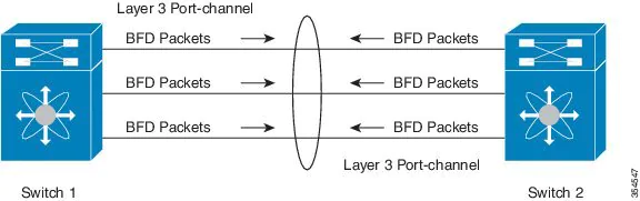
Micro Bidirectional Forwarding Detection
Beginning with Cisco APIC Release 5.2(3), APIC supports Micro BFD, as defined in IETF RFC 7130. When Bidirectional Forwarding Detection (BFD) is configured on a port channel, keep-alive packets are sent on any available member link. The failure of a single member link might not be detected, because the keep-alive packets can merely traverse a remaining link. Micro BFD is an enhancement to BFD that establishes individual BFD sessions on each member link of a port channel, as shown in the following figure.
Guidelines and limitations for Micro BFD:
- Micro BFD can run simultaneously with multi-hop BFD on the same port channel, but not with single-hop BFD.
- Micro BFD is a single-hop BFD implementation. It does not function if a Layer 2 switch exists between the main port channel on a switch and the switch's peer.
- Micro BFD is not supported on first-generation leaf switches. First-generation switches are those that do not contain a suffix, such as -EX or -FX, in the PID (product identifier).
- Micro BFD is supported only on the routed interface over a port channel.
- Client protocols can run on a sub-interface on the same port-channel where Micro BFD is enabled.
- Micro BFD is not supported on FEX ports or fabric ports.
- BFD Echo is not supported on Micro BFD sessions.
- On a dual IP stack port channel (IPv4 and IPv6) with Micro BFD enabled, you must configure Micro BFD with either an IPv4 address or an IPv6 address but not both. You cannot have both IPv4 and IPv6 Micro BFD sessions.
Open Authorization 2.0 support
Open Authorization (OAuth) 2.0 is an open-standard authorization protocol. OAuth 2.0 allows you to access an application (Service Provider or SP) that is trusted or approved by an Identity Provider (IdP). OAuth 2.0 uses authorization tokens to provide identity and authorization claims to the consumer application. Beginning with Cisco APIC Release 5.2(3), OAuth 2 server can be used to set up an application (such as, Cisco APIC) as an identity server that authenticates users using single sign-on.
Cisco release notes document points to the Cisco APIC Security guide for further reading on this topic, but I wasn't able to find anything related in there.
Rogue/COOP exception list
The rogue/COOP exception list enables you to specify the MAC address of endpoints for which you want to have a higher tolerance for endpoint movement with rogue endpoint control before the endpoints get marked as rogue. Endpoints in the rogue/COOP exception list get marked as rogue only if they move 3000 or more times within 10 minutes. After an endpoint is marked as rogue, the endpoint is kept static to prevent learning. The rogue endpoint is deleted after 30 seconds.
Guidelines and Limitations for the Rogue/COOP Exception List
The following guidelines and limitations apply when using the rogue/COOP exception list:
- The MAC address exception list feature works on Layer 2 bridge domains (bridge domains without IP routing enabled). This is because on a Layer 3 bridge domain (a bridge domain with IP routing enabled), if there are IP addresses moving along with MAC addresses, the IP addresses would end up being marked rogue first and both the IP and MAC address would then be quarantined.
- For a Layer 3 bridge domain, disable dataplane IP address learning per subnet for specific IP addresses that you want to exclude from rogue endpoint control.
For information about the dataplane IP address learning per subnet feature, see the Cisco APIC Layer 3 Networking Configuration Guide. - You are expected to have a full understanding of what kind of MAC addresses are being added to this list. You are responsible for ensuring that the MAC addresses in this list do not contribute to excessive moves in the overall fabric.
- You can add up to 100 MAC addresses to the exception list, fabric-wide.
- The exception list exemption on leaf switches applies only when rogue endpoint control is enabled. When rogue endpoint control is disabled, the MAC address exception list is used only by COOP dampening.
- The rogue/COOP exception list can only contain MAC addresses in a bridge domain and not IP addresses in a VRF instance. However, an IP address-only move can still cause the IP address to be marked as rogue if it meets the regular rogue endpoint control criteria.
- To mask out IP address rogue detection and marking based on data path traffic, you can use bridge domain subnet learn disable. Bridge domain subnet learn disable stops Cisco ACI from learning the IP address location at each move.
Security GUI screen enhancements
The security screens in the GUI are enhanced to show more information about the contract consumers and providers, and now include the ability to filter the data and view the resolved paths for an EPG or contract.
For more information, see the online help pages for the System > Security and Tenants > tenant_name > Security screens.
Specifying a transport protocol for a syslog remote destination
You can now specify a transport protocol to use for sending the syslog messages when you create a syslog remote destination.
Again the Release notes points to the Cisco APIC Basic Configuration Guide for the details on this change, but nothing was found related in there. Probably the document is not updated yet.
Support for Layer 3 multicast on L3Outs with SVI
Layer 3 multicast on an L3Out SVI adds support for enabling PIM on L3Out SVIs. This allows the ACI border leaf switch configured with an L3Out SVI to establish PIM adjacencies with an external multicast router or firewall.
An L3Out SVI is an interface type where a Layer 3 SVI interface is configured on every border leaf switch where the SVI is deployed. When PIM is enabled on an L3Out that is configured with an SVI, the PIM protocol will be enabled on the border leaf switch that is part of the SVI. All SVIs will then form PIM adjacencies with each other and any external PIM-enabled devices.
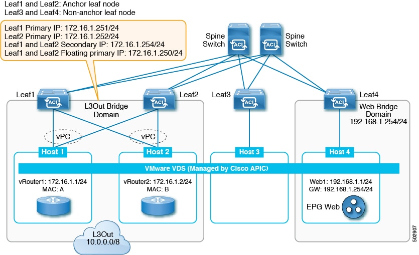
Support for multiple encapsulations for L3Outs with SVI
Prior to release 5.2(3), L3Outs configured with SVIs are limited to one VLAN encapsulation for each external bridge domain. However, with the introduction of floating L3Outs in release 4.2(1), there are scenarios where multiple VLAN encapsulations are needed for the same external bridge domain.
Beginning with release 5.2(3), support is now available for using different external VLAN encapsulations, where all of the different external encapsulation instances are treated as part of a single Layer 2 domain. An L3Out configured with multiple SVIs, each using a different encapsulation, can be grouped into a single external bridge domain. This single external bridge domain will use a single VXLAN network identifier (VNID) and will be a single broadcast domain. The SVIs configured with different encapsulations can use IP addresses in the same subnet.
Support for Prometheus Node Exporter
Support is now available for monitoring metrics using the Prometheus Node Exporter. The Prometheus Node Exporter provides visibility to a wide variety of hardware and kernel-related metrics, where it collects technical information from Linux nodes, such as CPU, disk, and memory statistics.

time-range REST API query option for viewing log record objects
Beginning with Cisco APIC release 5.2(3), with the new API query option time-range that is supported only for log record objects, the Cisco APIC can respond to the API query for the log record objects much faster. The Cisco APIC GUI also uses the time-range option for improved performance. This new query option for log record objects are not used in the CLI commands such as show faults history or show events.
USB port on Cisco ACI-mode switches can be disabled
Beginning in the Cisco Application Centric Infrastructure (ACI) 5.2(3) release, you can disable the USB port on a Cisco ACI-mode switch. If you have disabled the USB port, then when the switch is rebooted, the switch boots using the last known operating system image in the bootflash instead of using an image on a connected USB device. This feature provides an extra layer of protection in the event that someone power cycles the switch to try to boot the switch from a USB image that contains malicious code.
The USB port is enabled by default. You can configure a switch-level policy to disable the USB port on specific switches, or update the default USB configuration policy to disable USB port on all switches.
You can verify if someone tried to boot from the USB port by running the following command:
leaf1# show system reset-reason
*************** module reset reason (1) *************
0) At 2021-09-01T12:04:10.165-07:00
Reason: reset-due-to-no-boot-from-usb-policy
Service:module reloaded
Version: 15.2(3a)
In this example output, the reason shows that someone tried to boot from the USB port, but because the USB port was disabled, the switch instead booted automatically with the last known good image in the bootflash.
Resolved issues
CSCvs97029
All the external prefixes from VRF-A could be leaked to VRF-C even when an inter-VRF ESG leak route is configured for a specific prefix.
CSCvy17113
When there are two or more service graph associated contracts between the same pair of consumer and provider EPGs, and each contract is associated to a different Instp (by virtue of service graph configuration), imported/VRF-leaked Instp routes/subnets would not get cleaned up when one of those contracts is deleted from the list of contracts under the EPG. Imported routes/subnets would get cleaned up when the last contract between that EPG pair is deleted. There should be no impact to the traffic forwarding. This issue is about the cleanup of leaked routes.
CSCvy21881
An upgrade fails due to an incompatible target version. The upgradeStatusStr for maintUpgJob is empty, due to which the GUI is not able to show the correct state.
CSCvy29992
On the Cisco APIC CLI, the moconfig commit command triggers a "No such file or directory" error. The command successfully commits the changes, but the fact that this error shows up results in confusion for the end user.
CSCvy33994
On the Cisco APIC CLI, using the moset command to set an managed object attribute to the same value results in the following error: [Errno 1] Operation not permitted.
CSCvy85417
The show catalog is empty, which causes all switch discovery to fail because there is no catalog information present.
Compatibility information
Cisco NX-OS
15.2(3)
Cisco AVS
5.2(3)SV3(4.10)
Cisco UCS Manager
2.2(1c) or later is required for the Cisco UCS Fabric Interconnect and other components, including the BIOS, CIMC, and the adapter.
CIMC HUU ISO
- 4.1(3c) CIMC HUU ISO (recommended) for UCS C220/C240 M5 (APIC-L3/M3)
- 4.1(3b) CIMC HUU ISO for UCS C220/C240 M5 (APIC-L3/M3)
- 4.1(2b) CIMC HUU ISO (recommended) for UCS C220/C240 M4 (APIC-L2/M2)
- 4.1(1g) CIMC HUU ISO for UCS C220/C240 M4 (APIC-L2/M2) and M5 (APIC-L3/M3)
- 4.1(1f) CIMC HUU ISO for UCS C220 M4 (APIC-L2/M2) (deferred release)
- 4.1(1d) CIMC HUU ISO for UCS C220 M5 (APIC-L3/M3)
- 4.1(1c) CIMC HUU ISO for UCS C220 M4 (APIC-L2/M2)
- 4.0(4e) CIMC HUU ISO for UCS C220 M5 (APIC-L3/M3)
- 4.0(2g) CIMC HUU ISO for UCS C240 M4 and M5 (APIC-L2/M2 and APIC-L3/M3)
- 4.0(2g) CIMC HUU ISO for UCS C220 M4 and M5 (APIC-L2/M2 and APIC-L3/M3)
- 4.0(1a) CIMC HUU ISO for UCS C220 M5 (APIC-L3/M3)
- 3.0(4l) CIMC HUU ISO (recommended) for UCS C220/C240 M3 (APIC-L1/M1)
- 3.0(4d) CIMC HUU ISO for UCS C220/C240 M3 and M4 (APIC-L1/M1 and APIC-L2/M2)
- 3.0(3f) CIMC HUU ISO for UCS C220/C240 M4 (APIC-L2/M2)
- 3.0(3e) CIMC HUU ISO for UCS C220/C240 M3 (APIC-L1/M1)
- 2.0(13i) CIMC HUU ISO
- 2.0(9c) CIMC HUU ISO
- 2.0(3i) CIMC HUU ISO


Member discussion