Cisco APIC 5.1(3e) released

Release 5.1(3e) became available on February 1, 2021.
New software features
Support for the BGP Domain-Path feature for loop prevention
BGP routing loops might occur in certain situations due to various conditions, such as:
- Intentional disabling of existing BGP loop prevention mechanisms, such as AS Path checks
- Route leaks across different VRFs or VPNs
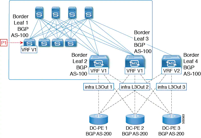
Following is an example scenario where a BGP routing loop might occur:
1. A prefix P1 received from a BGP IP L3Out peer is advertised in the ACI fabric using the Multiprotocol Border Gateway Protocol (MP-BGP).
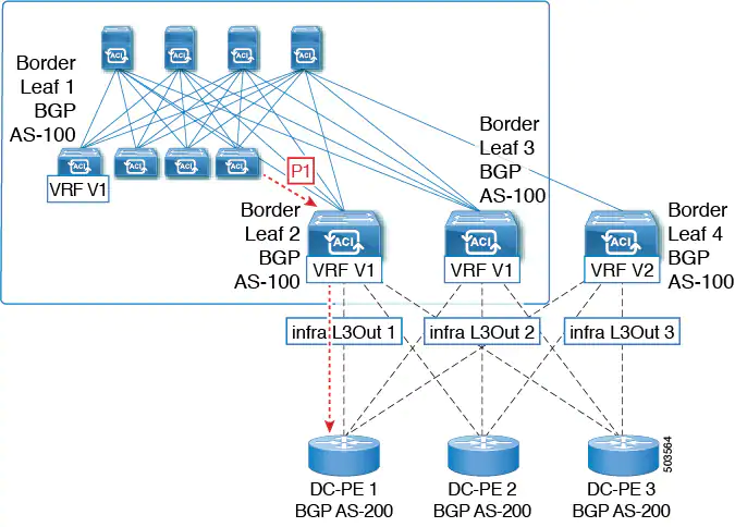
2. As a transit case, this prefix can be advertised out externally through an SR-MPLS infra L3Out.
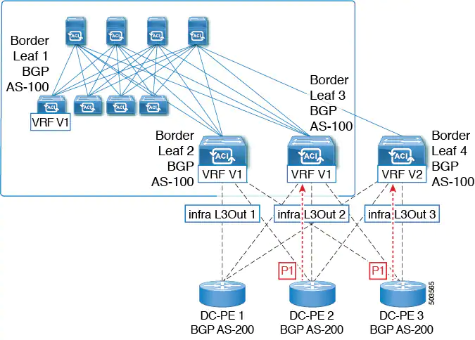
3. This prefix could then be imported back into the ACI fabric from the core, either in the same VRF or in a different VRF.
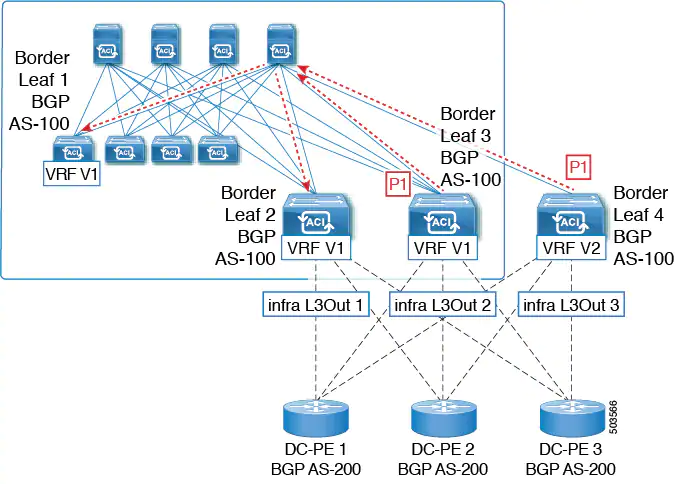
4. A BGP routing loop would occur when this imported prefix is then advertised back to the originating switch, either from the same VRF or through a leak from a different VRF.
Beginning with Release 5.1(3), the new BGP Domain-Path feature is available, which helps with BGP routing loops in the following ways:
- Keeps track of the distinct routing domains traversed by a route within the same VPN or extended VRFs, as well as across different VPNs or VRFs
- Detects when a route loops back to a VRF in a domain where it has already traversed (typically at a border leaf switch that is the stitching point between domains, but also at an internal switch, in some cases)
- Prevents the route from getting imported or accepted when it would lead to a loop
Within an ACI fabric, the VRF scope is global and is extended to all switches where it is configured. Therefore, a route that is exported out of a domain in a VRF is blocked from being received back into the VRF on any other switch.
The following components are used with the BGP Domain-Path feature for loop prevention:
- Routing domain ID: Every tenant VRF in an ACI site is associated with one internal fabric domain, one domain for each VRF in each SR-MPLS infra L3Out, and one domain for each IP L3Out. When the BGP Domain-Path feature is enabled, each of these domains is assigned a unique routing domain ID, in the format
Base:<variable>, where:Baseis the non-zero value that was entered in the Domain ID Base field in the BGP Route Reflector Policy page<variable>is a randomly-generated value specifically for that domain
- Domain path: The domain segments traversed by a route are tracked using a BGP domain path attribute:
- The domain ID of the VRF for the source domain where the route is received is prepended to the domain path
- The source domain ID is prepended to the domain path while re-originating a route across domains on the border leaf switches
- An external route is not accepted if any of the local domain IDs for the VRFs is in the domain path
- The domain path is carried as an optional and transitive BGP path attribute with each domain segment, represented as
<Domain-ID:SAFI> - The ACI border leaf switches prepend the VRF internal domain ID for both locally originated and external routes to track leaks within the domain
- A route from the internal domain can be imported and installed in a VRF on a node with a conflicting external domain ID to provide an internal backup or transit path
- For infra L3Out peers, the advertisement of a route to a peer is skipped if the domain ID of the peer domain is present in the domain path of the route (outbound check is not applicable for IP L3Out peers)
- The border leaf switches and non-border leaf switches will both process the domain path attribute
Notes:
- You can configure the BGP Domain-Path feature for loop prevention, or simply enable the configuration to send a received domain path, through the GUI or REST API. You cannot configure the BGP Domain-Path feature for loop prevention or enable the configuration to send a received domain path through the NX-OS style CLI.
- When upgrading to Release 5.1(3) from a previous release, if you have contracts configured for inter-VRF shared services, those contracts might not work as expected with the BGP Domain-Path feature for loop prevention because the BGP domain ID would not have been set in those contracts that were configured before you upgraded to Release 5.1(3). In those situations, delete the contract and then add the contract back, which will allow the BGP domain update to occur. This is only an issue when you have contracts that were configured prior to your upgrade to Release 5.1(3); this is not an issue when you create new contracts after you've completed the upgrade to Release 5.1(3).
Support for Layer 3 multicast routing on remote leaf switches
Beginning with release 5.1(3), support is available for Layer 3 multicast routing on remote leaf switches. Prior to this release, support was available for Layer 3 multicast routing in only single-pod, multi-pod, and multi-site topologies on local leaf switches.
There is no difference between the newly-supported remote leaf switches and the previously-supported local leaf switches with regards to the implementation of Layer 3 multicast routing through Cisco APIC or Cisco ACI Multi-Site Orchestrator. The main difference between the two is based on how traffic is forwarded:
- Layer 3 multicast between local leaf switches in a single fabric is forwarded as VXLAN multicast packets where the outer destination IP address is the VRF GIPo multicast address
- Layer 3 multicast packets sent to or sent by remote leaf switches are encapsulated as VXLAN unicast head-end replicated packets
When Layer 3 multicast routing is enabled for a VRF, the VRF GIPo multicast address is programmed on all leaf switches where the VRF is deployed. Layer 3 multicast packets will be forwarded across the pod or between pods as multicast packets and will be received by all leaf switches where the VRF is deployed. For remote leaf switches, the Layer 3 multicast packets will be forwarded using head-end replication to all remote leaf switches where the VRF is deployed. This head-end replication occurs on the pod or remote leaf where the multicast source is connected. For example, if the multicast source is connected to a local leaf switch, one of the spine switches in that pod will be selected to replicate these multicast packets to every remote leaf switch where the VRF is deployed, even if these remote leaf switches are associated with other pods. When a Layer 3 multicast source is connected to a remote leaf switch, the remote leaf switch will also use head-end replication to send a copy of the multicast packet to a spine in every pod as well as all other remote leaf switches where the VRF is deployed.
Multicast forwarding using head-end replication replicates the multicast packet as a separate unicast packet for every head-end replication tunnel. Layer 3 multicast in a remote leaf switch design should ensure that the IP network (IPN) where the remote leaf switches are connected has sufficient bandwidth to support multicast traffic requirements.
Remote leaf switches support L3Out connections with or without PIM enabled. All leaf switches in a VRF that have PIM-enabled L3Outs are eligible to send PIM joins from the fabric towards external sources and rendezvous points. When a multicast receiver connected to the fabric sends an IGMP join for a group, the fabric will select one of the PIM-enabled border leaf switches to send the join (known as the stripe winner). A remote leaf switch with a PIM-enabled L3Out can be selected as the stripe winner for a group even when the receivers for that group are connected to local leaf switches in the main pod. Due to potential sub-optimal forwarding of Layer 3 multicast traffic, deploying PIM-enabled L3Outs on remote leaf switches is not recommended.
Guidelines and Limitations:
- Pod redundancy is supported for Layer 3 multicast forwarding with remote leaf switches. If all spine switches in the pod where the remote leaf switch is associated fail, the remote leaf switch can establish control plane connectivity to spine switches in another pod.
- Remote leaf switches must have connectivity to at least one spine switch in any pod. Layer 3 multicast traffic will not be forwarded if the remote leaf switches lose connectivity to all spine switches. This includes Layer 3 multicast traffic between senders and receivers on the same leaf switch.
New IP SLA monitoring policy parameters
The IP SLA monitoring policy now has the following parameters:
- Request Data Size (bytes)
- Type of Service
- Operation Timeout (milliseconds)
- Threshold (milliseconds)
- Traffic Class Value
Additional auto-negotiation support
The auto-negotiation "On-Enforce" mode is now supported on the Cisco Nexus N9K-C93180YC-EX and N9K-C9364C-GX switches. All switches that support auto-negotiation now support additional speeds in the "On-Enforce" mode.
Resolved issues
CSCvq54761
The application EPG or the corresponding bridge domain's public subnet may be advertised out of an L3Out in another VRF instance without a contract with the L3Out under certain conditions.
CSCvv69041
There is traffic loss on SDA after deleting an overlapping subnet.
CSCvw87460
The leaf switch is listed as unsupported and the model name is truncated.
Compatibility information
Cisco NX-OS
15.1(3)
Cisco AVS
5.2(1)SV3(4.10)
Cisco UCS Manager
2.2(1c) or later is required for the Cisco UCS Fabric Interconnect and other components, including the BIOS, CIMC, and the adapter.
CIMC HUU ISO
- 4.1(1g) CIMC HUU ISO (recommended) for UCS C220/C240 M4 (APIC-L2/M2) and M5 (APIC-L3/M3)
- 4.1(1f) CIMC HUU ISO for UCS C220 M4 (APIC-L2/M2) (deferred release)
- 4.1(1d) CIMC HUU ISO for UCS C220 M5 (APIC-L3/M3)
- 4.1(1c) CIMC HUU ISO for UCS C220 M4 (APIC-L2/M2)
- 4.0(4e) CIMC HUU ISO for UCS C220 M5 (APIC-L3/M3)
- 4.0(2g) CIMC HUU ISO for UCS C240 M4 and M5 (APIC-L2/M2 and APIC-L3/M3)
- 4.0(2g) CIMC HUU ISO for UCS C220 M4 and M5 (APIC-L2/M2 and APIC-L3/M3)
- 4.0(1a) CIMC HUU ISO for UCS C220 M5 (APIC-L3/M3)
- 3.0(4l) CIMC HUU ISO (recommended) for UCS C220/C240 M3 (APIC-L1/M1)
- 3.0(4d) CIMC HUU ISO for UCS C220/C240 M3 and M4 (APIC-L1/M1 and APIC-L2/M2)
- 3.0(3f) CIMC HUU ISO for UCS C220/C240 M4 (APIC-L2/M2)
- 3.0(3e) CIMC HUU ISO for UCS C220/C240 M3 (APIC-L1/M1)
- 2.0(13i) CIMC HUU ISO
- 2.0(9c) CIMC HUU ISO
- 2.0(3i) CIMC HUU ISO


Member discussion