Cisco APIC 5.0(1k) released

Release 5.0(1k) became available on May 14, 2020.
New software features
Active/Active Layer1/Layer2 symmetric policy-based redirect design
The Layer1/Layer 2 devices in the service chain can now operate in an active/active symmetric policy-based redirect (PBR) design. Symmetric PBR is used to load balance traffic to individual devices based on the hash.
A Layer 1 device is typically called inline or wire mode and used for firewall and IPS if the service device is expected to perform security functions not participating in L2 or L3 forwarding.
A Layer 2 device is typically called transparent mode or bridged mode and used for firewall and IPS.
A Layer 3 device is typically called in a routed mode and used for router firewall and load balancer.
Prior to ACI release 4.1, PBR could be configured to redirect traffic to a L4-L7 device configured in Layer 3 device (Go-To) mode only. If L4-L7 device is Layer 1 or Layer 2 device such as transparent firewall, PBR couldn't be used, which means you could only deploy a L4-L7 device operating in Layer 1 or Layer 2 mode by using Service Graph and defining the L4-L7 device in Go-Through mode.
Starting from APIC release 4.1, PBR can be configured to redirect traffic to a L4-L7 device configured in Layer 1/ Layer 2 device mode as well. PBR can be used with inline IPS, transparent firewall, in addition to routed mode firewall.
As part of Layer 1/ Layer 2 PBR feature, APIC can verify whether the L4-L7 device is forwarding traffic by using L2 Ping packets for link layer tracking.
Differently from Go-Through mode, which can forward also non-IP traffic, Layer 1 / Layer 2 PBR is applicable to IP traffic only.
Additional modes and auto-negotiation for FEC
Forwarding Error Correction (FEC) encodes data in a redundant way to obtain reliable data transmission over a noisy channel. This release adds more FEC modes, including auto-negotiation of FEC.
Auto-negotiation is an optional function of the IEEE 802.3u Fast Ethernet standard that enables devices to automatically exchange information over a link about speed and duplex abilities. ACI switches support auto-negotiation on these port types:
- 10/25/40/100Gbps on copper passive cables
- 10Gbps native copper ports
You can select from the following auto-negotiation modes:
- off: Auto-negotiation is disabled.
- on: Auto-negotiation is enabled on RJ45 ports. This is the default.
- on-enforce: Auto-negotiation is enabled on copper passive cables. This mode is available beginning with Cisco ACI Release 5.0(1).
Auto-negotiation includes the auto-negotiation protocol exchange and link training. 10/40/100Gbps ports support fixed speed auto-negotiation. Ports with 25Gbps direct-attach-cable (DAC) copper cables support speed auto-negotiation, in which the switch advertises both 10Gbps and 25Gbps speeds. In this case, the negotiated speed is the fastest common speed advertised from both peers.
Ports with 25Gbps DAC copper cables support negotiation of forwarding error correction (FEC) as part of the auto-negotiation protocol exchange. Switches advertise their supported FEC modes, and both peers agree upon the best available mode.
Guidelines and Restrictions for Auto-Negotiation
- When auto-negotiation is enabled, it should be enabled on both peers – the ACI switch and the link partner.
- Auto-negotiation is not supported on 4x10Gbps and 4x25Gbps breakout copper ports.
- The on-enforce mode is not supported on N9K-C93180YC-EX, N9K-C93600CD-GX (Ports 1-24), and N9K-C9364C-GX (Ports 1-64).
The supported FEC modes are as follows:
- AUTO-FEC:
- CL74-FC-FEC: Supports 25 Gbps speed.
- CL91-RS-FEC: Supports 25 and 100 Gbps speeds.
- CONS16-RS-FEC: Supports 25 Gbps speed.
- IEEE-RS-FEC: Supports 25 Gbps speed.
- KP-FEC: Supports 4x100 Gbps (KP1) or 400 Gbps (KP4).
- Disable-FEC: Disables FEC.
- Inherit: The switch uses FEC based on the port transceiver type. All 25G transceivers (Copper and Fiber) have FC-FEC enabled. All interfaces with 100G transceivers have RS-FEC enabled.
The default is "Inherit."
Switch support for FC-FEC
| Switch | Details |
|---|---|
| N9K-93180YC-FX | Supported for 25Gbps ports |
| N9K-93180YC-EX | Supported for 25Gbps ports |
| N9K-C9348GC-FXP | Supported for 25Gbps ports |
| N9K-C93240YC-FX2 | Supported for 25Gbps ports |
| N9K-C93360YC-FX2 | Supported for 25Gbps ports |
Switch support for RS-FEC
| Switch | Details |
|---|---|
| N9K-93180YC-FX | Supported for 100G speed |
| N9K-93180YC-EX | Supported for 100G speed |
| N9K-93108TC-FX | Supported for 100G speed |
| N9K-93108TC-EX | Supported for 100G speed |
| N9K-C93180LC-EX | Supported for 100G speed |
| N9K-C9364C | Supported for 100G speed |
| N9K-C9348GC-FXP | Supported for 100G speed |
| N9K-C9336C-FX2 | Supported for 100G speed |
| N9K-C93240YC-FX2 | Supported for 100G speed |
| N9K-C9332C | Supported for 100G speed |
| N9K-C9358GY-FXP | Supported for 100G speed |
| N9K-C93360YC-FX2 | Supported for 100G speed |
| N9K-C93216TC-FX2 | Supported for 100G speed |
| N9K-C9316D-GX | Supported for 100G speed |
| N9K-C93600CD-GX | Supported for 100G speed |
| N9K-C9364C-GX | Supported for 100G speed |
| N9K-X9732C-EX (LC) | Supported for 100G speed |
| N9K-X9736C-FX (LC) | Supported for 100G speed |
Default FEC support for switches
EX Switches
| Optics | Default Auto-FEC | Inherit |
|---|---|---|
| 10G-CU1,3,5M | Disable FEC | Disable FEC |
| 25G-CU1M | FC-FEC (CL74) | FC-FEC (CL74) |
| 25G-CU2M | FC-FEC (CL74) | FC-FEC (CL74) |
| 25G-CU3M | FC-FEC (CL74) | FC-FEC (CL74) |
| 25G-CU5M | FC-FEC (CL74) | FC-FEC (CL74) |
| 40G-CU1,3,5M | Disable FEC | Disable FEC |
| 100G-CU1,3,5M | RS-FEC (CL91) | RS-FEC (CL91) |
FX switches and above
| Optics | Default Auto-FEC | Inherit |
|---|---|---|
| 10G-CU1,3,5M | Disable FEC | Disable FEC |
| 25G-CU1M | Disable FEC | FC-FEC (CL74) |
| 25G-CU2M | Disable FEC | FC-FEC (CL74) |
| 25G-CU3M | FC-FEC (CL74) | FC-FEC (CL74) |
| 25G-CU5M | IEEE-RS-FEC | FC-FEC (CL74) |
| 40G-CU1,3,5M | Disable FEC | Disable FEC |
| 100G-CU1,3,5M | RS-FEC (CL91) | RS-FEC (CL91) |
Avoiding suboptimal traffic from Cisco ACI internal endpoints to a floating L3Out
Prior to Cisco APIC release 5.0(1), even if an external router is connected under a non-anchor leaf node, traffic from a Cisco ACI internal endpoint to a floating L3Out goes to an anchor leaf node and then goes to the external router through the non-anchor leaf node, which is not an optimal traffic path. Beginning in Cisco APIC release 5.0(1), you can avoid this suboptimal traffic path by using next-hop propagation.
Avoiding this suboptimal path requires configuring next-hop propagation and direct host advertisement route-control profiles.
Next-hop propagation is supported with BGP only.

BFD multihop support
BFD multihop provides subsecond forwarding failure detection for a destination with more than one hop and up to 255 hops. Cisco APIC now supports BFD multihop for IPv4 and IPv6 in compliance with RFC5883.
BFD multihop sessions are set up between a unique source and destination address pair. A BFD multihop session is created between a source and destination rather than with an interface, as with single-hop BFD sessions.
BFD multihop sets the TTL field to the maximum limit supported by BGP, and does not check the value on reception. The ACI leaf has no impact on the number of hops a BFD multihop packet can traverse, but the number of hops is limited to 255.
Guidelines and Limitations for BFD Multihop
- The default transmit and receive interval timers for BFD multihop are 250 ms, and the default detection multiplier is 3.
- Echo mode is not supported for BFD multihop.
C-bit support for BFD
Cisco ACI now supports C-bit-aware bidirectional forwarding detection (BFD). The C-bit on incoming BFD packets determines whether BFD is dependent or independent of the control plane.
DUO two-factor authentication on Cisco APIC
Cisco APIC supports multi-factor authentication with DUO security. Cisco APIC offers second factor (2F) authentication on top of an organization’s existing authentication, which could be on-premises or cloud-based.
Second factor authentication with Duo occurs once the user has finished the authentication with the organization's primary authentication source.
Duo supports three types of 2F authentication methods after you complete authentication with the primary authentication source:
- Notification push on mobile using the Duo mobile app on smartphones.
- Phone call on your registered phone or mobile numbers.
- Passcode that is generated on the Duo mobile app.
The user is authenticated using the following servers:
- The Duo proxy RADIUS server uses the multi-factor authentication in Cisco APIC to authenticate a distributed client/server system using RADIUS PAP primary authentication method.
- The Duo proxy LDAP server uses the multi-factor authentication in Cisco APIC to authenticate a remote server using Cisco AVPair or Group Maps authentication method.
Endpoint security groups
An endpoint security groups (ESG) is a logical entity that contains a collection of physical or virtual network endpoints. The endpoints can be classified based on attributes, such as an IPv4 or IPv6 address spanning across bridge domains in the VRF table. An ESG is a security construct that has certain match criteria for creating segmentation, and uses contracts or policies to define the security stance. An ESG separates forwarding from security.
Endpoint Security Groups (ESGs) are the new network security component in Cisco ACI. Although the endpoint groups (EPGs) have been providing the network security in Cisco ACI, EPGs have to be associated to a single bridge domain (BD) and used to define security zones within a BD. This is because the EPGs define both forwarding and security segmentation at the same time. The direct relationship between the BD and an EPG limits the possibility of an EPG to spanning more than one BD. This limitation of EPGs is resolved by using the new ESG constructs.

The Application endpoint group (fvAEPg) object that represents an EPG has a direct relationship with the bridge domain object (fvBD) that represents the Layer 2 broadcast domain. This is illustrated in the above figure, in the first three columns.
An ESG is a logical entity that contains a collection of physical or virtual network endpoints. In addition, an ESG is associated to a single VRF (Virtual Routing and Forwarding) instead of BD. This allows the definition of a security zone that is independent of the BDs (the fourth column of Figure, illustrates this point). Just as the EPGs divide a BD into security zones, the ESGs divide the VRF into security zones.
The EPG policy embeds both forwarding and security logic. For example, an EPG provides not only a security zone based on VLAN, but also a VLAN binding on leaf node interfaces. Also, a contract on the EPG is used to enforce the security and determine which leaf nodes the BD subnet should be deployed on, and which subnets to be leaked to which VRF in the case of VRF route leaking (i.e. shared service). On the contrary, an ESG is used only to enforce security using the contracts while the forwarding logics are handled by other components. With an ESG, the routing logic such as BD subnets deployment and VRF route leaking are moved to VRF level. The VLAN binding on leaf node interfaces are still handled at EPG level.
An ESG is a security construct that has certain match criteria to define which endpoint belongs to the ESG, and uses contracts or policies to define the security stance. The match criteria are called the ESG selectors that are based on attributes, such as an IPv4 or IPv6 address spanning across BDs in the associated VRF. For Cisco APIC, release 5.0(1), the available matching criteria is the IP address or the subnet of an endpoint.
The contract usage in the ESGs is the same as the EPGs. Endpoints that belong to the same ESG can communicate without the need for a contract. To enable communication between endpoints that belong to different ESGs, you need to configure contracts between the ESGs. For the communication with devices outside of the Cisco ACI fabric, you need to configure a contract between the L3Out external EPG (l3extInstP) and the ESG. You can also use a Layer 4 to Layer 7 service graph in conjunction with a contract between the ESGs. However, contracts between an EPG and an ESG are not supported.
Link flap policies
You can create a link flap policy in interface policies, which sets the state of a port to "error-disable" after the port flaps for specified number of times during a specified interval of time.
Link flap is a situation in which a physical interface on a switch continually goes up and down over a period of time. The cause is usually related to a bad, unsupported, or non-standard cable or Small Form-Factor Pluggable (SFP), or is related to other link synchronization issues, and the cause can be intermittent or permanent.
A link flap policy specifies when to disable a switch port due to link flapping errors. In a link flap policy, you specify maximum number of times that a port of a switch can flap within a specified time span. If the port flaps more than the specified number of times in the specified time span, the port is given the "error-disable" state. The port remains in this state until you perform a manual flap on the port using the Cisco Application Policy Infrastructure Controller (APIC) to disable and enable the port.
Multicast filtering
Beginning with Cisco APIC release 5.0(1), you can use the multicast filtering feature to filter multicast traffic from two directions: source filtering at the first-hop route and receiver filtering at the last-hop route.
ACI supports control plane configurations that can be used to control who can receive multicast feeds and from which sources. The filtering options can be IGMP report filters, PIM join or prune filters, PIM neighbor filters, and Rendezvous Point (RP) filters. These options rely on control plane protocols, namely IGMP and PIM.
In some deployments, it may be desirable to constrain the sending and/or receiving of multicast streams at the data plane level. For example, you may want to allow multicast senders in a LAN to only send to specific multicast groups or to allow receivers in a LAN to only receive specific multicast groups originated from all the possible sources or from specific sources.
Per-leaf switch RBAC
A fabric administrator can now assign a physical node, such as a leaf switch, to a security domain. Only a user with node management privileges within the security domain can configure nodes assigned to that domain. The user has no access to nodes outside of the security domain, and users in other security domains have no access to the node assigned to the security domain.
To create or modify configurations on a node assigned to the security domain, a user in that domain must also be assigned to domain all with the port-mgmt role.
When configuring a local user who will manage ports on an assigned node, you must grant the user the port-mgmt role in domain all, and the admin role in the security domain to which the node is assigned. Both roles must have the Role Privilege Type configured as Write.
Guidelines and Limitations for Security Domains and Node Rules
When configuring security domains and node rules, follow these guidelines and limitations. In this section, a "restricted node user" is a user in a restricted security domain to which a node has been assigned.
- When upgrading from an earlier release to Cisco APIC Release 5.0(x), you must reconfigure any rules, policies, or roles that use the more granular earlier privileges.
- When downgrading from Cisco APIC Release 5.0(x) to an earlier release, you must manually edit and retain default roles. Roles modified under Cisco APIC Release 5.0(x) are retained.
- A spine switch can't be assigned using RBAC node rules.
- When creating RBAC node rules, you should not assign a node to more than one security domain.
- A restricted node user can configure only policies. An admin user should perform node configuration and troubleshooting.
- A restricted node user can access default system-created managed objects (MOs).
- A restricted node user can view fabric-level fault counts in the Fault Dashboard.
- A restricted node user can view node-level faults, such as those from AAA servers, NTP servers, and DNS servers.
- If an admin or nonrestricted domain user associates a relationship policy to an access policy created by a restricted node user, that policy will be visible to the restricted node user.
- You can't configure a restricted node user using the CLI.
- The
port-mgmtrole contains predefined access policy MOs. You can add more MOs using the procedure in Configuring a Custom Privilege.
Physical domains
Physical domains enable you to use the floating L3Out feature with virtual routers without VMM domain integration or to use a physical router without L3Out logical interface path configurations.
Policy-based redirect with an L3Out service EPG
The unidirectional policy-based redirect is now supported with the other connector in an L3Out, regardless if the L3Out is the provider or consumer connector and regardless if the L3Out is last node or not.
Prior to Cisco APIC Release 4.1(2), both the consumer and the provider connectors of the PBR node must be in bridge domains, as shown in the following illustration, even though the policy-based redirect is not required on an interface of PBR node.

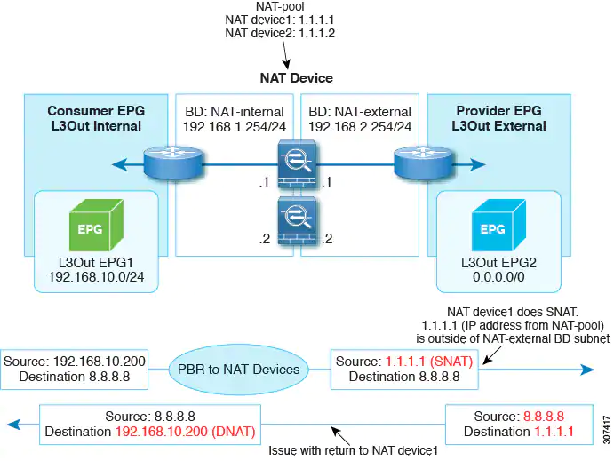
An example situation where policy-based redirect with L3Out would be a useful configuration with symmetric PBR with multiple network address translation NAT devices, as shown in the following illustration.
In this situation, for L3Out internal to L3Out external traffic, symmetric PBR is used to load balance traffic to one of the PBR nodes. In addition, the IP address from the NAT-pool is outside of the service bridge domain subnet range. The return traffic needs to go back to the same node in this situation, but for releases prior to Cisco APIC Release 4.1(2), the L3Out cannot be used on the NAT-external side because if the PBR is used on the service node connector, the other service node connector must be in the bridge domain as well.
Beginning with Cisco APIC Release 4.1(2), uni-directional policy-based redirect with L3Out is supported, as shown in the following illustration. In this example, policy-based redirect is enabled in the consumer connector in the bridge domain, but the policy-based redirect is not enabled on the provider connector in the L3Out.
This design is supported only when L3Out is the provider connector of the last service node.

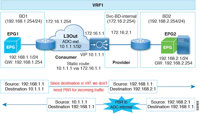
Starting from Cisco APIC Release 5.0(1), the uni-directional policy-based redirect is supported with the other connector in L3Out, regardless L3Out is provider or consumer connector and regardless L3Out is last node or not. This includes the case where the load balancer has VIP outside of local subnet on the consumer side of the service node, as shown in the following illustration. The policy-based redirect is not supported in L3Out.

In the following illustration example, the incoming traffic from consumer endpoint to the VIP is forwarded to the load balancer connected to the L3Out based on the routing table. Then, the traffic is forwarded to provider endpoint. The return traffic from the provider endpoint to the consumer endpoint is redirected to the provider side of the service node because of PBR.
Guidelines and Limitations
Following are the guidelines and limitations for policy-based redirect with L3Out:
- Use a specific L3Out EPG subnet if there are other L3Out EPGs in the same VRF; otherwise, the other L3Outs might be used for EPG classification by mistake.
- Ensure that IP translation occurs on the service node. In case NAT is not properly done on the service node, then it could cause a loop.
Port bring-up delay
When you configure a link level policy, you can set the Port bring-up delay (milliseconds) parameter, which specifies a time in milliseconds that the decision feedback equalizer (DFE) tuning is delayed when a port is coming up. The delay begins when an incoming signal is detected, and can help avoid CRC errors in a specific circumstance. You should set the delay only as required; in most cases, you do not need to set a delay.
Restricting infra VLAN traffic
For stronger isolation between hypervisors in the fabric, you can now restrict infra VLAN traffic to only network paths specified by a set of infra security entry policies.
When you enable this feature, each leaf switch limits Infra VLAN traffic from compute nodes to allow only VXLAN traffic. The switch also limits traffic to leaf nodes to allow only OpFlex, DHCP/ARP/ICMP, and iVXLAN/VXLAN traffic. APIC management traffic is allowed on front panel ports on the Infra VLAN.
This feature is disabled by default.
Rewrite source MAC address when creating a Layer 4 to Layer 7 policy-based redirect
When the rewrite source MAC address feature is enabled and traffic is redirected through a policy-based redirect policy, the traffic will carry the redirected destination service bridge domain SVI MAC address instead of its original source MAC address.
Secondary IP address and floating secondary IP address
You can use a secondary IP address as a common IP address for anchor leaf nodes. A floating secondary IP address enables additional floating IP address subnets on the same floating switch virtual interface (SVI).
SNMP and syslog configuration in the First Time Setup wizard
The First Time Setup wizard assists the user in configuring a Cisco APIC for the first time. This release adds initial configuration of Syslog monitoring destinations and of SNMP external management and trap destinations.
Segment routing multiprotocol label switching handoff
Prior to Cisco APIC release 5.0(1), when setting up a Cisco ACI fabric connected to a data center provider edge (DC-PE) for a configuration with a multi-tenant network, you need multiple VRFs and a routing protocol for each VRF. You also need to dedicate an interface for each VRF, where the interface is either a physical interface or a logical interface. This configuration uses IP handoff and is typically called VRF-Lite.
Beginning with Cisco APIC release 5.0(1), you can now set up a Cisco ACI fabric connection with a DC-PE using segment routing (SR) Multiprotocol Label Switching (MPLS) handoff.
Upgrade enhancements
Various enhancements have been made to the upgrade process, including:
- The restriction on the number of pods that you can upgrade in parallel has been relaxed so that you can upgrade multiple pods at the same time for pod nodes in Multi-Pod configurations. Switches in a Multi-Pod configuration that are part of the same maintenance group can now be upgraded in parallel.
- Upgrades or downgrades might be blocked if certain issues are present.
- Additional information is provided in the GUI for each stage of the APIC upgrade or downgrade process.
- The default concurrency in a group has changed from 20 to unlimited (the default number of leaf or spine switches that can be upgraded at one time is unlimited).
- When upgrading nodes in an upgrade group using the GUI, Download Progress field is available in the Work pane, which provides a status on the progress of the download of the firmware for the node upgrade.
New hardware features
- On the Cisco N9K-C9336C-FX2 switch, you can now apply a breakout configuration on ports 1 through 34, which can give up to 136 (34*4) server or downlink ports.
- The Cisco Nexus 9508-FM-G (N9K-C9508-FM-G) fabric module that supports the N9K-X9736C-FX and N9K-X9736Q-FX line cards.
- The Cisco Nexus 9508-FAN2 (N9K-C9508-FAN2) fan tray that supports the N9K-C9508-FM-G fabric modules.
- The Cisco Nexus 9508-FAN-PWR (N9K-9508-FAN-PWR) blank fan power card that supports the N9K-C9508-FAN2 fan trays.
Resolved issues
CSCvu18072
The Cisco APIC setup script will not accept an ID outside of the range of 1 through 12, and the Cisco APIC cannot be added to that pod. This issue will be seen in a multi-pod setup when trying add a Cisco APIC to a pod ID that is not between 1 through 12.
CSCvd66359
The Port ID LLDP Neighbors panel displays the port ID when the interface does not have a description. Example: Ethernet 1/5, but if the interface has description, the Port ID property shows the Interface description instead of the port ID.
CSCvf70362
This enhancement is to change the name of "Limit IP Learning To Subnet" under the bridge domains to be more self-explanatory.
Original:
Limit IP Learning To Subnet: [check box]
Suggestion:
Limit Local IP Learning To BD/EPG Subnet(s): [check box]
CSCvg00627
A tenant's flows/packets information cannot be exported.
CSCvg35344
Requesting an enhancement to allow exporting a contract by right clicking the contract itself and choosing "Export Contract" from the right click context menu. The current implementation of needing to right click the Contract folder hierarchy to export a contract is not intuitive.
CSCvh52046
This is an enhancement to allow for text-based banners for the Cisco APIC GUI login screen.
CSCvi20535
When a VRF table is configured to receive leaked external routes from multiple VRF tables, the Shared Route Control scope to specify the external routes to leak will be applied to all VRF tables. This results in an unintended external route leaking. This is an enhancement to ensure the Shared Route Control scope in each VRF table should be used to leak external routes only from the given VRF table.
CSCvj56726
The connectivity filter configuration of an access policy group is deprecated and should be removed from GUI.
CSCvk18014
The action named 'Launch SSH' is disabled when a user with read-only access logs into the Cisco APIC.
CSCvm42914
This is an enhancement request to add policy group information to the properties page of physical interfaces.
CSCvn12839
Error mac.add.ress not a valid MAC or IP address or VM name is seen when searching the EP Tracker.
CSCvp26694
A leaf switch gets upgraded when a previously-configured maintenance policy is triggered.
CSCvp62048
New port groups in VMware vCenter may be delayed when pushed from the Cisco APIC.
CSCvq57942
In a RedHat OpenStack platform deployment running the Cisco ACI Unified Neutron ML2 Plugin and with the CompHosts running OVS in VLAN mode, when toggling the resolution immediacy on the EPG<->VMM domain association (fvRsDomAtt.resImedcy) from Pre-Provision to On-Demand, the encap VLANs (vlanCktEp mo's) are NOT programmed on the leaf switches.
This problem surfaces sporadically, meaning that it might take several resImedcy toggles between PreProv and OnDemand to reproduce the issue.
CSCvq63415
Disabling dataplane learning is only required to support a policy-based redirect (PBR) use case on pre-"EX" leaf switches. There are few other reasons otherwise this feature should be disabled. There currently is no confirmation/warning of the potential impact that can be caused by disabling dataplane learning.
CSCvq80820
A previously-working traffic is policy dropped after the subject is modified to have the "no stats" directive.
CSCvq96516
There is an event manager process crash.
CSCvr08257
The out-of-band ping output in the output of the cluster health tool intermittently shows 'Ping failed' due to a bug in the code that parses the ping output. It does not imply an underlying connectivity issue between the APICs in the cluster.
CSCvr10020
Fault alarms get generated at a higher rate with a lower threshold. There is no functional impact.
CSCvr12971
The Cisco APIC GUI produces the following error messages when opening an EPG policy:
Received Invalid Json String.
The server returned an unintelligible response.
This issue might affect backup/restore functionality.
CSCvr19693
When configuring local SPAN in access mode using the GUI or CLI and then running the show running-config monitor access session <session> command, the output does not include all source span interfaces.
CSCvr62453
When a Cisco ACI fabric upgrade is triggered and a scheduler is created and associated to the maintenance group, the scheduler will remain associated to the maintenance group. If the version is changed in the maintenance group, it will trigger the upgrade. This enhancement is to avoid unwanted fabric upgrades. Post-upgrade, the association of the scheduler should be removed from the maintenance group after the node upgrade reaches 100%.
CSCvr73902
The GUI allows the target version to be changed in an existing upgrade group even when an upgrade is in progress.
CSCvr85945
The description field does not appear in the subnet IP address tables.
CSCvr86018
Some endpoints in the Cisco APIC GUI endpoint tracker have no state transitions, even when they have moved.
When using icurl to get data on the same endpoints, state transitions are shown.
CSCvs03055
While configuring a logical node profile in any L3Out, the static routes do not have a description.
CSCvs04899
When you run the show vpc map command in the Cisco APIC CLI, it only prints the column headers, but none of the vPC information. If you go to the leaf switch CLI and run the show vpc extended command, it will show the vPCs there.
CSCvs11202
After exiting Maintenance (GIR) mode, the switch reloads automatically after 5 minutes without warning. This enhancement will provide messaging in the GUI to indicate that the reload is expected.
CSCvs13857
L3Out encapsulated routed interfaces and routed interfaces do not have any monitoring policy attached to them. As a result, there is no option to change the threshold values of the faults that occur due to these interfaces.
CSCvs14967
There is high memory usage by the svc_ifc_ae.bin process (AE service). The AE process uses more than 3 GB and the memory usage constantly increases for the process.
Check for PERF-STATS-LOG in the svc_ifc_ae.bin.log. If you see a value more than 1000 for Configs:, then you are hitting this bug. This file is located at /var/log/dme/log.
CSCvs16317
An app does not get fully removed from all Cisco APICs.
CSCvs29556
When logging into the Cisco APIC using apic#fallback\\user, the Error: list index out of range log message displays and the lastlogin command fails. There is no operational impact.
CSCvs31335
App techsupport collection does not work sometimes when triggered from the Cisco APIC GUI.
CSCvs33720
Connections to a Cisco APIC might get blocked with the NET::ERR_CERT_REVOKED error.
CSCvs53247
OpenStack supports more named IP protocols for service graph rules than are supported in the Cisco APIC OpenStack Plug-in.
CSCvs56642
This is an enhancement request for schedule-based Tech Support for leaf and spine switches.
CSCvs62693
The Name column of the the output of the show zoning-rule CLI command that is executed on a leaf switch running a 14.x release does not populate all of the expected contracts names. This issue makes it difficult to identify which rule ID is associated to which contract from the show zoning-rule command that is executed on a given leaf switch.
CSCvs81421
It is difficult to configure interface selectors in the GUI, because "interface policy group" window is too narrow.
CSCvs81429
It is difficult to configure interface selectors, because there is no search option available for the interface policy group window.
CSCvs81944
The following example shows UNIX time in the subject header:
Subject: Configuration import/export job 2020-01-27T09-00-16 finished with status: success
Created: 1580144423366
ContentType: plain/text
CSCvs92682
OID 1.3.6.1.4.1.9.9.117.2.0.0.2 in v1 SNMP trap cefcPowerStatusChange by Cisco APIC is observed.
CSCvt02599
Cisco ACI CNI is enabling SNAT for subnets that are "local" to the cluster VRF table. A local subnet is defined as a subnet in the same VRF table as the Kubernetes cluster.
CSCvt39746
Cisco APIC interfaces e2/3 & e2/4 persist in the GUI and the MIT after disabling and enabling the port channel on the VIC.
CSCvt41841
A stale prefix entry remains that is associated with an old VRF table.
CSCvt44854
- Leaf or spine switch is stuck in
downloading-boot-scriptstatus. The node never fully registers and does not become active in the fabric. - You can check the status by running
cat /mit/sys/summary | grep stateon the CLI of the spine or leaf switch:
If the state is set todownloading-boot-scriptfor a long period of time (> 5 minutes) you may be running into this issue. - Checking the policy element logs on the spine or leaf switch will confirm if the bootscript file cannot be found on the Cisco APIC:
1. Change directory to/var/log/dme/log.
2. Grep allsvc_ifc_policyelem.logfiles fordownloadUrl - failed, error=HTTP response code said error
If you see this error message, check to make sure all Cisco APICs have the node bootscript files located in/firmware/fwrepos/fwrepo/boot.
CSCvt48790
There is a stale fvIfConn entry after physically removing the ESXi host after a host is removed from the datacenter or VMware vCenter.
CSCvt49260
The 'Primary VLAN for Micro-Seg' field does not show without putting a check in the Allow Micro-Segmentation check box.
CSCvt50687
This is an enhancement to remove the "Learned End-Points" tab under the EPG or ESG Operational tab in the Cisco APIC GUI.
The "Learned End-Points" tab should be removed because it is has duplicate information from the "Client End-Points" tab.
The "Client End-Points" tab shows not only endpoints that are actually learned by Cisco ACI leaf switches, but also endpoints that are reported by other VMM controllers such as VMware vCenter, but not yet learned in the Cisco ACI hardware.
Therefore, to see only the endpoints that are learned, use a filter with the "learned" flag in the "Learning Source" column of the "Client End-Points" tab.
CSCvt55566
In the Cisco APIC GUI, after removing the Fabric Policy Group from "System > Controllers > Controller Policies > show usage", the option to select the policy disappears, and there is no way in the GUI to re-add the policy.
CSCvt64925
Changes to a Cisco APIC configuration are no longer pushed to the Cisco APIC.
CSCvt67097
In the Cisco APIC GUI, external EPGs under L2Out and L3Out in tenants are called "External Network Instance Profile". This is the official name for object (l2extInstP and l3extInstP). However, these are typically referred to as external EPGs. This is an enhancement to update the GUI label from "External Network Instance Profile" to "External EPG".
CSCvt67279
After VMware vCenter generates a huge amount of events and after the eventId increments beyond 0xFFFFFFFF, the Cisco APIC VMM manager service may start ignoring the newest event if the eventId is lower than the last biggest event ID that Cisco APIC received. As a result, the changes to virtual distributed switch or AVE would not reflect to the Cisco APIC, causing required policies to not get pushed to the Cisco ACI leaf switch. For AVE, missing those events could put the port in the WAIT_ATTACH_ACK status.
CSCvt68786
A Cisco ACI Virtual Edge EPG is not programmed on a port channel toward the blade switch after it is deleted and recreated.
CSCvt70316
SNMP poll/walk to the Cisco APIC does not work . The error message "unknown username" is received.
CSCvt83895
There are no auto completion for commands sent to fabric nodes, such as fabric <node-id> show ?. The following commands do not give any output:
show controller
show switch
CSCvt92961
A TEP endpoint can expire on the leaf switch if the host does not respond on a unicast ARP refresh packet initiated by the leaf switch.
CSCvu01818
There is a message in the Cisco APIC GUI saying that vleaf_elem has restarted several times and may not have recovered, and there are core files of the vleaf_elem process.
CSCvu12478
Fabric > Inventory > Topology > Topology shows wrong Cisco APIC counts (Active + Standby) in different pods.
CSCvu15639
In "Math Routing policy" mode, the default-import route-map is missing.
Known issues
CSCvj26666
The show run leaf|spine <nodeId> command might produce an error for scaled up configurations.
CSCvj90385
With a uniform distribution of EPs and traffic flows, a fabric module in slot 25 sometimes reports far less than 50% of the traffic compared to the traffic on fabric modules in non-FM25 slots.
CSCvm71833
Switch upgrades fail with the following error: Version not compatible.
CSCvq39764
When you click Restart for the Microsoft System Center Virtual Machine Manager (SCVMM) agent on a scaled-out setup, the service may stop. You can restart the agent by clicking Start.
CSCvq58953
One of the following symptoms occurs:
- App installation/enable/disable takes a long time and does not complete.
- Nomad leadership is lost. The output of the acidiag scheduler logs members command contains the following error:
"Error querying node status: Unexpected response code: 500 (rpc error: No cluster leader)"
CSCvr89603
The CRC and stomped CRC error values do not match when seen from the APIC CLI compared to the APIC GUI. This is expected behavior. The GUI values are from the history data, whereas the CLI values are from the current data.
CSCvs19322
Upgrading Cisco APIC from a 3.x release to a 4.x release causes Smart Licensing to lose its registration. Registering Smart Licensing again will clear the fault.
CSCvs92309
A custom QoS policy at the LifP-level configuration is not supported for an MPLS L3Out.
CSCvt56254
Stats that should update every 15 minutes instead get updated after between 15 minutes and 20 minutes.
CSCvt85167
A Service graph that has service EPGs with vzAny as the consumer and provider gets the Global PCTag with EPGs/ESGs.
Issues without ID
- If you use the REST API to upgrade an app, you must create a new firmware.OSource to be able to download a new app image.
- In a multipod configuration, before you make any changes to a spine switch, ensure that there is at least one operationally "up" external link that is participating in the multipod topology. Failure to do so could bring down the multipod connectivity. For more information about multipod, see the Cisco Application Centric Infrastructure Fundamentals document and the Cisco APIC Getting Started Guide.
- With a non-english SCVMM 2012 R2 or SCVMM 2016 setup and where the virtual machine names are specified in non-english characters, if the host is removed and re-added to the host group, the GUID for all the virtual machines under that host changes. Therefore, if a user has created a micro segmentation endpoint group using "VM name" attribute specifying the GUID of respective virtual machine, then that micro segmentation endpoint group will not work if the host (hosting the virtual machines) is removed and re-added to the host group, as the GUID for all the virtual machines would have changed. This does not happen if the virtual name has name specified in all english characters.
- A query of a configurable policy that does not have a subscription goes to the policy distributor. However, a query of a configurable policy that has a subscription goes to the policy manager. As a result, if the policy propagation from the policy distributor to the policy manager takes a prolonged amount of time, then in such cases the query with the subscription might not return the policy simply because it has not reached policy manager yet.
- When there are silent hosts across sites, ARP glean messages might not be forwarded to remote sites if a 1st generation ToR switch (switch models without -EX or -FX in the name) happens to be in the transit path and the VRF is deployed on that ToR switch, the switch does not forward the ARP glean packet back into the fabric to reach the remote site. This issue is specific to 1st generation transit ToR switches and does not affect 2nd generation ToR switches (switch models with -EX or -FX in the name). This issue breaks the capability of discovering silent hosts.
- Typically, faults are generally raised based on the presence of the BGP route target profile under the VRF table. However, if a BGP route target profile is configured without actual route targets (that is, the profile has empty policies), a fault will not be raised in this situation.
- MPLS interface statistics shown in a switch's CLI get cleared after an admin or operational down event.
- MPLS interface statistics in a switch's CLI are reported every 10 seconds. If, for example, an interface goes down 3 seconds after the collection of the statistics, the CLI reports only 3 seconds of the statistics and clears all of the other statistics.
CIMC version recommendations
- 4.1(1f) CIMC HUU ISO (recommended) for UCS C220/C240 M4 (APIC-L2/M2) and M5 (APIC-L3/M3)
- 4.1(1d) CIMC HUU ISO for UCS C220 M5 (APIC-L3/M3)
- 4.1(1c) CIMC HUU ISO for UCS C220 M4 (APIC-L2/M2)
- 4.0(4e) CIMC HUU ISO for UCS C220 M5 (APIC-L3/M3)
- 4.0(2g) CIMC HUU ISO for UCS C240 M4 and M5 (APIC-L2/M2 and APIC-L3/M3)
- 4.0(2g) CIMC HUU ISO for UCS C220 M4 and M5 (APIC-L2/M2 and APIC-L3/M3)
- 4.0(1a) CIMC HUU ISO for UCS C220 M5 (APIC-L3/M3)
- 3.0(4l) CIMC HUU ISO (recommended) for UCS C220/C240 M3 (APIC-L1/M1)
- 3.0(4d) CIMC HUU ISO for UCS C220/C240 M3 and M4 (APIC-L1/M1 and APIC-L2/M2)
- 3.0(3f) CIMC HUU ISO for UCS C220/C240 M4 (APIC-L2/M2)
- 3.0(3e) CIMC HUU ISO for UCS C220/C240 M3 (APIC-L1/M1)
- 2.0(13i) CIMC HUU ISO
- 2.0(9c) CIMC HUU ISO
- 2.0(3i) CIMC HUU ISO


Member discussion