GRE over IPSEC between Cisco and Mikrotik

Preamble
I wasted too much time searching for a solution. Not many articles describe the approach with a NATted peer. So I had to build a small lab and get into experiments to find the right, and what's more important, a working solution.
What you're experiencing with the wrong configuration
You will not have reachability via the GRE interface. With the proper ACL configured on the public interface of the Cisco router you will see the GRE packets arriving.
The task
- We have to build GRE over IPSEC (L3 routed) connectivity between Cisco and Mikrotik devices.
- The Mikrotik device is behind a NAT.
- Cisco device has the GRE tunnel configured with a tunnel protection profile. No crypto maps involved.
The diagram and details
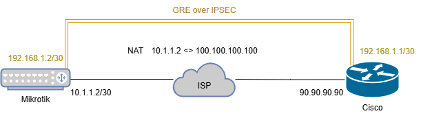
The Mikrotik device has the ether2 interface connected to the ISP. The address of the ether2 interface is 10.1.1.2/30. The GRE interface on the Mikrotik device should have the 192.168.1.2/30 address.
The Cisco device has the Public IP assigned to its GigabitEthernet0/1 interface with the address 90.90.90.90. The GRE interface on the Cisco device should have the 192.168.1.1/30 address.
Cisco config
IKEv2
crypto ikev2 proposal IKEV2-PROPOSAL
 encryption aes-cbc-256
 integrity sha256
 group 14
!
crypto ikev2 policy IKEV2-POLICY
 match fvrf any
 match address local 90.90.90.90
 proposal IKEV2-PROPOSAL
!
crypto ikev2 keyring IKEV2-KEYRING
 peer MT
  address 100.100.100.100
  pre-shared-key chepuha
 !
!
crypto ikev2 profile IKEV2-PROFILE
 match fvrf any
 match identity remote address 100.100.100.100 255.255.255.255
 identity local address 90.90.90.90
 authentication remote pre-share
 authentication local pre-share
 keyring local IKEV2-KEYRING
!
crypto ikev2 nat keepalive 10
All is simple here. From the Cisco device's point of view, we have a neighbor with a public IP. Configuring a strong, up-to-date IKE proposal followed by policy, keyring for PSK auth, and a profile.
To prevent the deletion of NAT entries in the absence of any traffic, the NAT keepalive is configured with crypto ikev2 nat keepalive.
IPSEC
crypto ipsec transform-set IPSEC-TS-AES esp-aes 256 esp-sha256-hmac
 mode tunnel
!
crypto ipsec fragmentation after-encryption
!
crypto ipsec profile GREoIPSEC
 set transform-set IPSEC-TS-AES
 set pfs group14
 set ikev2-profile IKEV2-PROFILE
Configuring strong encryption for the 2nd phase. Enabling fragmentation to be applied after encryption (it's not important for a demonstration).
Many articles strongly suggest using the transport mode for a transform set. The transport mode will not work correctly for a NAT case. You need the tunnel mode to encapsulate the original IP header.
Tunnel interface and Internet interface
interface Tunnel1
 ip address 192.168.1.1 255.255.255.252
 ip mtu 1400
 ip tcp adjust-mss 1360
 tunnel source 90.90.90.90
 tunnel destination 100.100.100.100
 tunnel protection ipsec profile GREoIPSEC
!
ip access-list extended ACL-Gi0/1-IN
 permit icmp any any
 permit esp any any
 permit udp any any eq isakmp non500-isakmp
 deny   ip any any log
!
interface GigabitEthernet0/1
 ip address 90.90.90.90 255.255.255.0
 ip access-group ACL-Gi0/1-IN in
Apply the IPSEC profile to the tunnel interface. The tunnel mode gre ip is applied to the interface by default. To be sure that we're allowing only the IPSEC traffic to our public interface, apply an inbound ACL that allows isakmp, esp and icmp. Anything other will be dropped and logged.
esp proto will never hit the ACL as peers will be using NAT-T thus all traffic will be exchanged through the UDP/4500 (non500-isakmp).Mikrotik config
GRE and interfaces
/interface gre
add allow-fast-path=no dont-fragment=inherit local-address=100.100.100.100 \
    mtu=1400 name=gre-tunnel1 remote-address=90.90.90.90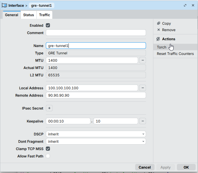
Disable the Fast Path option here. Also, it's important to set the Local Address to `100.100.100.100`.
IKE/IPSEC
/ip ipsec policy group
add name=cisco-vpn
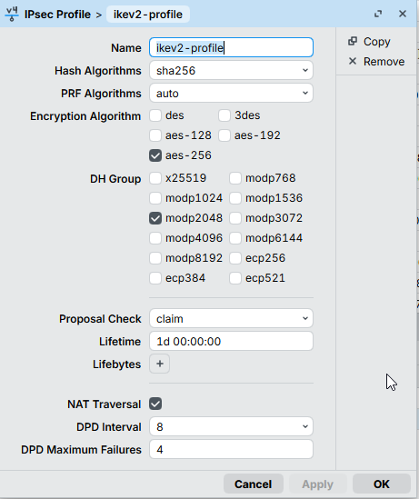
/ip ipsec profile
add dh-group=modp2048 enc-algorithm=aes-256 hash-algorithm=sha256 name=\
ikev2-profile proposal-check=claim
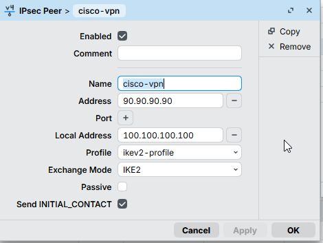
/ip ipsec peer
add address=90.90.90.90/32 exchange-mode=ike2 local-address=100.100.100.100 \
name=cisco-vpn profile=ikev2-profile
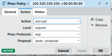
/ip ipsec proposal
add auth-algorithms=sha256 enc-algorithms=aes-256-cbc name=ipsec-proposal \
pfs-group=modp2048
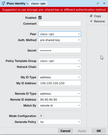
/ip ipsec identity
add my-id=address:100.100.100.100 peer=cisco-vpn policy-template-group=\
cisco-vpn remote-id=address:90.90.90.90
/ip ipsec policy
add dst-address=90.90.90.90/32 peer=cisco-vpn proposal=ipsec-proposal \
protocol=gre src-address=100.100.100.100/32 tunnel=yes
It's important to set the Local Address here to 100.100.100.100.

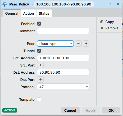
The Tunnel setting is a must!
The bridge
/interface bridge
add arp=disabled fast-forward=no name=bridge1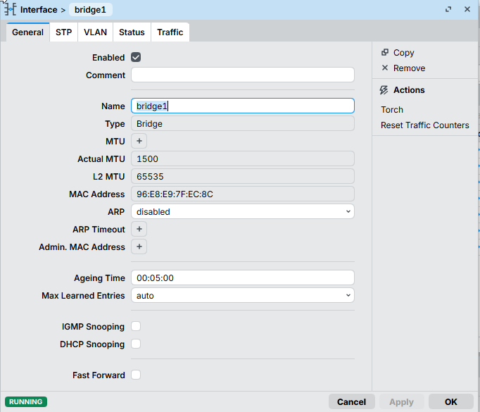
Cherry on a cake - the bridge interface! Very important piece of the whole configuration.
As the Mikrotik device is behind a NAT, the local IPSEC security association looks like this:
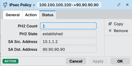
And the Cisco ones like this:
local crypto endpt.: 90.90.90.90, remote crypto endpt.: 100.100.100.100The traffic-selector though, has to be the same as on the Cisco device, otherwise the Phase2 SA will be rejected with the NO_PROPOSAL_CHOOSEN message.
To handle this, we have:
- A tunnel mode for IPSEC policy
- An IPSEC policy source set to
100.100.100.100
And here comes the bridge interface. We need something to have this 100.100.100.100 address locally on the Mikrotik. You may think of this bridge interface as a loopback on the Cisco device.
To be sure we're not breaking anything, the bridge interface has to:
- not be bridged with any physical interfaces
- have the ARP disabled
IP addresses
/ip address
add address=10.1.1.2/30 interface=ether2 network=10.1.1.0
add address=100.100.100.100 interface=bridge1 network=100.100.100.100
add address=192.168.1.2/30 interface=gre-tunnel1 network=192.168.1.0
Here we are assigning IP addresses to the corresponding interfaces.
The results
Cisco-side
VPN#ping 192.168.1.2
Type escape sequence to abort.
Sending 5, 100-byte ICMP Echos to 192.168.1.2, timeout is 2 seconds:
!!!!!
Success rate is 100 percent (5/5), round-trip min/avg/max = 3/4/5 ms
IT'S ALIVE!
VPN#show crypto ikev2 sa
 IPv4 Crypto IKEv2  SA

Tunnel-id Local                 Remote                fvrf/ivrf            Status
1         90.90.90.90/4500      100.100.100.100/4500  none/none            READY
      Encr: AES-CBC, keysize: 256, PRF: SHA256, Hash: SHA256, DH Grp:14, Auth sign: PSK, Auth verify: PSK
      Life/Active Time: 86400/4651 sec
Check the IKEv2 SA
VPN#show crypto session remote 100.100.100.100 detail
Crypto session current status

Code: C - IKE Configuration mode, D - Dead Peer Detection
K - Keepalives, N - NAT-traversal, T - cTCP encapsulation
X - IKE Extended Authentication, F - IKE Fragmentation
R - IKE Auto Reconnect, U - IKE Dynamic Route Update
S - SIP VPN

Interface: Tunnel1
Profile: IKEV2-PROFILE
Uptime: 01:21:32
Session status: UP-ACTIVE
Peer: 100.100.100.100 port 4500 fvrf: (none) ivrf: (none)
      Phase1_id: 100.100.100.100
      Desc: (none)
  Session ID: 1300
  IKEv2 SA: local 90.90.90.90/4500 remote 100.100.100.100/4500 Active
          Capabilities:(none) connid:2 lifetime:22:38:28
  IPSEC FLOW: permit 47 host 90.90.90.90 host 100.100.100.100
        Active SAs: 2, origin: crypto map
        Inbound:  #pkts dec'ed 558 drop 0 life (KB/Sec) 4325592/3042
        Outbound: #pkts enc'ed 85 drop 0 life (KB/Sec) 4325601/3042
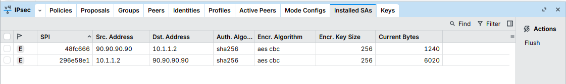
Tunnel and IPSEC SA stats
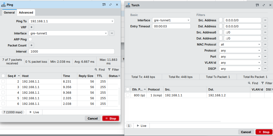
Mikrotik-side


Member discussion